New features 2023 Series - Electrical CAD
Electro Graphics releases the latest 2023 Series of electrical and photovoltaic design software. Here are the most important features and enhancements introduced in the electric CAD CADelet, iDEA, Eplus.
See all new features 2023:
Eplus and iDEA are based on the new AutoCAD OEM 2023 engine
One of the main novelties of the 2023 version of iDEA and Eplus 64-bit is the update from version 2021 to version 2023 of the Autodesk AutoCAD® OEM engine on which the two electrical CADs are based.
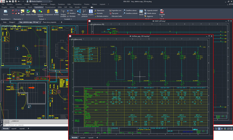
Thanks to the new floating drawing windows it is now possible to view drawing windows side by side or on multiple monitors without launching another instance of iDEA or Eplus. Whoever works with the dual screen can finally also move the drawing windows from one screen to another by easily exiting the iDEA/Eplus application; just select the tab with the file name and drag the window, which detaches and becomes a floating window, to be moved to the desired position also on the other monitor. Some benefits of the floating drawing window feature are:
• You can view multiple design files at once without switching between tabs.
• You can move one or more design files to another monitor.
A new button in the application status bar (bottom right) lets to quickly access the options and preferences that affect the drawing and processing of diagrams and electrical installations in CADelet/Smart/iDEA/Eplus:
• Network locations
• Configuration parameters of the current drawing
• Graphic environment preferences
CADelet supports AutoCAD 2023
• CADelet line software is now compatible with AutoCAD version 2010 to 2023 64 bit.
• Smart line software is now compatible with AutoCAD LT version 2010 to 2019 64 bit.
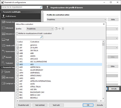
Assignment of the preferential manufacturers used in the job order, with a dedicated filter in all archive access operations
The configuration parameters of a project, or order, include preferences and customizations that affect the drawing environment and data processing in all Electro Graphics software (CADelet, Smart, iDEA, Eplus, Ampère ProfessionalTabula, Cablo When creating a job order, it is possible to choose the configuration or work profile, as an alternative to the default one. The job order drawings automatically assume the parameters of the selected configuration, which can always be modified at any time within the work environment.
In the configuration parameters associated with an order it is now possible to set the profile of the active manufacturers.
The assignment of an active manufacturer profile affects the display and search filters of all the archives in the projects located within the job order to which the configuration has been assigned: this means that if a project has an active manufacturer profile, only the elements related to the enabled constructors are displayed.
In the material and protection archives it is always possible to temporarily deactivate the active profile to allow particular searches.
Automatic dynamic tracking of connections upon symbol insertion, with assignment of wire characteristics
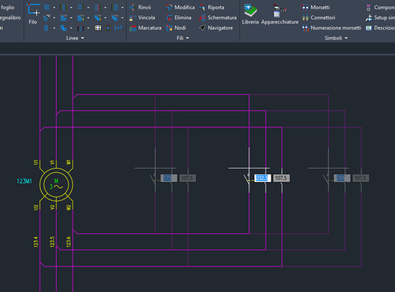
The new Automatic Connections function facilitates the connection of a symbol to power lines, while inserting it into the sheet. The function operates while inserting symbols from the library: it automatically recognizes the presence of electrical lines and symbols in the current sheet and, based on the detected circuit situation, offers a preview of the connections that will be made upon confirmation by the designer.
The Automatic Connections function can be deactivated and activated at any time, even during the execution of the symbol insertion command, using the F5 key, or using the appropriate button in the application status bar.
Automatic recognition of the phases when inserting symbols on a multi-line diagram
By inserting a symbol from the library, the automatic connection function searches the current sheet for electric lines orthogonal to the connection direction of the pins and shows the preview of the connection lines. By moving the symbol near the horizontal or vertical power lines, the connections to the pins of the symbol are automatically snapped towards them. When the symbol is at the hooking distance to the power lines, the function displays a tool window that allows customization of the connection characteristics; the connection of the phases is defined automatically by the software but it is always possible to set it manually. Finally, the connecting wires to the pins take on the electrical characteristics of the lines they connect to: section, colour, designation, typology...
Interactive management of location and function in diagrams, with recognition of functional zones or perimeter locations
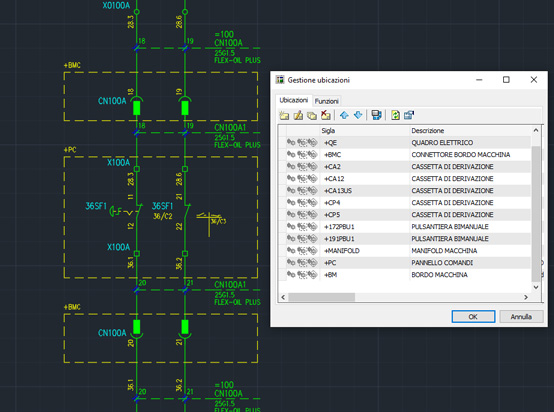
In order for a plant to be effectively designed, built, maintained or used, the system and system-related information is usually divided into parts. Each of these parts can be divided into other parts. This division into parts and the management of those parts is called structuring. In compliance with the CEI EN 61346-1 standard, in Electro Graphics software, it is possible to manage a location- and function-oriented structuring. The Location management window allows you to define the locations and functions into which the components of the electrical diagram in the project are divided.
The area of a sheet of the wiring diagram, to be reserved for symbols characterized by a specific location and/or function, can be visually delimited by a box characterized by the name of the location/function to which they belong. With the new version it is possible to allow the software to automatically assign the location and function to the symbols, based on their position within the boxes. In particular, the symbols assume the location or function of a box when:
- they are inserted or moved within a box;
- the shape of a box is changed to include symbols not previously contained within the box.
Activation, operation and graphical characteristics are all customizable.
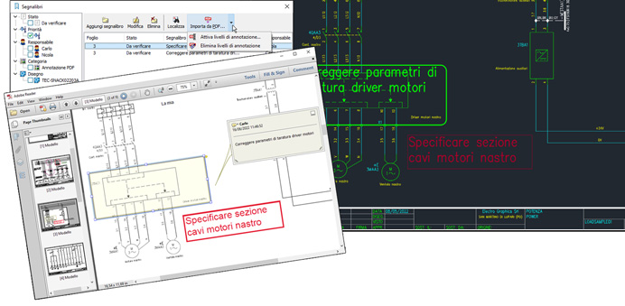
Importing annotations from PDF multi-sheet diagrams into the drawing (manual sketches, info texts,...)
Applications for viewing PDF files also allow you to add notes, comments and graphic elements to it that are useful for sharing information between those who consult the document.
In terms of interoperability and collaborative work, the import of annotations present on a PDF file on the electrical diagram is a valid tool that allows information to be passed between operators in the workshop or construction site, who usually have the electrical diagram available in PDF format , and the designer who creates the drawing in CAD.
Through a new function available in CADelet/Smart/iDEA/Eplus, in the Bookmarks window, it is possible to import directly into the drawing all the annotations present in the PDF file with their information content as created by the field operators. The function imports annotations of the following types from a PDF file.
• Comment text
• Text box
• Highlight
• Pencil
• Rectangle
• Oval
Annotations, including text and graphics, are imported as a bookmark, which can be viewed and searched using the Bookmarks window features. A bookmark is a container of descriptive properties assigned to a schema sheet as attached notes.
Following several imports, it is possible to generate a table with the history of the annotations managed on the schema.
In the Bookmarks window, the Save to PDF command has now been added: it allows you to quickly save the selected sheets in a PDF document.
Another added utility is the Copy to clipboard function which allows you to copy the information visible in the current list and then paste it into a document opened in a generic text editor (Notepad, Word,...).
Cross-references between any symbolic elements of the diagram and their representation in the PDF of the diagram
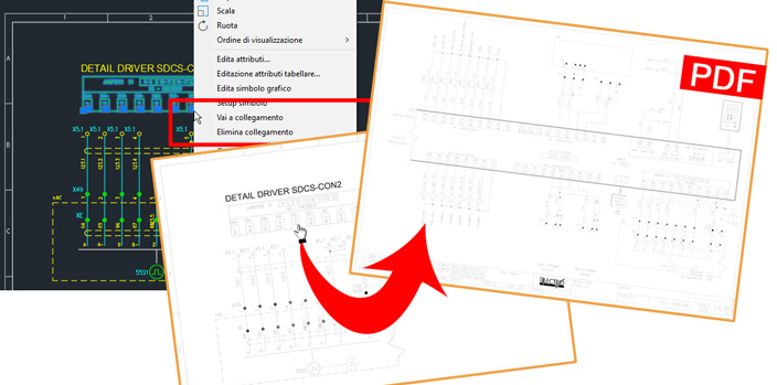
Sometimes, in some points of the electrical diagram, it is useful to show construction details or connection details that refer to components or parts of the diagram in other sheets or other drawings of the project. For example, sheet 23 shows a detail of the wiring of some pins of a card drawn on sheet 142.
A new function available in CADelet/Smart/iDEA/Eplus creates a relationship between a component and the block showing its detail.
The referenced component can be a symbol from the Schematic Library or User Catalog with the standard attribute set. The detailed details can also be normal AutoCAD blocks, more or less complex, drawn and saved in the drawing or in the user catalog library or in an external file.
The details that refer to the same component can, moreover, be more than one and placed in different points of the diagram.
To facilitate navigation between the different points of the diagram, it is possible to jump between the detail view and the referenced component view, with a simple click.
This feature is especially useful when publishing the electrical diagram to PDF for viewing in non-CAD environments.
The generation of the PDF file adds a clickable link on the detail block area to quickly locate the referenced component in the electrical diagram, with a simple click.
New features on modular connectors, with the possibility of connections on the frame
The modular connectors are a type of electrical connection elements made available by some manufacturers that allow to aggregate within a common container, the frame, a set of several connectors or plugs designed for assembly in the frame.
The management of the connectors in the electrical CAD CADelet/Smart/iDEA/Eplus and in Cablo, allows you to define the modular connectors as several connectors assembled to one element, defined as a Frame, from which they assume Mark, Location and Function. After tracking in the project, their aggregation is displayed in the connector detail tables and in the connector list table.
In Archives Cavetteria, it is now possible to assign pins also to modular connector frames; in fact, the presence of the PE connection is typical. Insertion in the graphical environment takes place as for normal connectors. The summary table of the modular connector also shows the pinout of the chassis if present.
PLC: management of additional profiles for automatic assignment of operand numbering
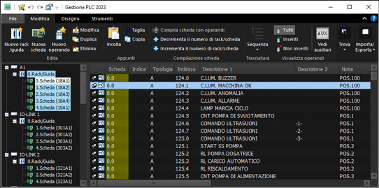
The Reassign operand address function in PLC Management allows you to assign the address of the operands in the project. In version 2023, the following options have been added.
Multi-level numbering
Some types of cards use multi-level numbering, such as SLAVE.BYTE.BIT . To manage these numbers, it is possible to define customizable and dynamic prefixes and suffixes that can be obtained on the basis of data extracted from the boards and racks. Currently it is possible to use the following information: unit code, rack and card index, notes field of the parent card or notes field of the parent rack (the latter allow you to save customized information).
Continuous numbering for inputs and outputs
This option automatically allows continuous numbering between multiple input and output cards.
Renumbering operands for racks and for selected units
In combination with the new operand renumbering options it is now possible to initiate the address update for multiple selected units or even for multiple card racks. Select all the cards to be renumbered from the list and start the Reassign address command.
Multiple insertion of cards
For plotting in drawing cards and operands, it is now possible to start drawing for several selected units or for all operands of selected cards.
PLC: identification and representation of the connectors integrated in the boards
In the representation of a board or component in the electrical diagram, it may be necessary to identify the connectors that group the connection terminals (pins).
To this end, for each pin of the symbols it is possible to edit the Component connector attribute, which allows you to correctly identify multiple pins of the same symbol, also having the same value but belonging to different connectors, in the diagrams and in the various printouts, elaborated graphics, nameplate exports etc. available in Cablo and in the CADelet/Smart/iDEA graphic environment.
Extending and customizing the data managed in diagram reviews
The Sheet review and Diagram review functions, available in CADelet/Smart/iDEA/Eplus also in previous versions, allow the identification and management of revisions of single sheets of an electrical diagram or of the entire diagram.
In the 2023 version it is possible to customize all the characteristics of the tables including the choice of labels to be reported and the title of the sheet, as already possible for other tables available in CADelet/Smart/iDEA/Eplus. It is also possible to filter the data before drawing the table based on one or more columns of your choice and export the table to XLS spreadsheet or CSV formatted text file.
Synoptic extensions, with the management of the symbolic elements of the information scheme taken from user drawings
Sometimes a block diagram or a P&ID diagram in dwg format contains information (abbreviations, descriptions and technical data) that must be reported within the wiring diagram.
Furthermore, it may happen that these data vary with the design choices and it becomes necessary to synchronize all the information that has already been reported in the diagram.
To facilitate these operations, new functions allow you to define arbitrary attributes as data source for the electrical diagram and create rules for compiling the abbreviation.
Alignment with Ampère Professional
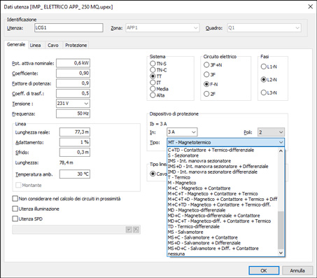
CADelet/Smart/iDEA/Eplus are updated according to the innovations introduced in Ampère Professional, the electrical grid calculation software. The editing of units in CAD is now updated with the new management of protections: possibility of compose up to 4 distinct elements and a greater number of possible combinations.
For coupling elements, it is now possible to match a base protection and a coupling element belonging to different manufacturers. In addition, the list of types of protection that can be chosen as a coupled component has been expanded. The typee list now includes differential, relay release, magnetic, thermal, fuse.
Generation of single-line diagrams from an Ampère project with identification and management of elements in the field
The electrical utilities managed in the Electro Graphics software, both Ampère for calculation and CADelet, Smart, iDEA and Eplus for design, have always been organized into zones and panels to which they belong.
The grid mesh in Ampère 2023 highlights the units physically placed inside a switchboard or cabinet from those placed outside the casing but assigned to it anyway.
Normally, the units with only protections are physically in the internal part of a switchgear, and the pipes determine the external boundary. Downstream of a pipeline, the users connected (in any case assigned to the same switchboard) are considered physically external to the switchboard, and are also called elements in the field.
The differentiation of "element inside the switchgear or in the field" can also be considered in the design of the single-line diagram of users through a special option.
New ways of sorting the tables generated by network management
In the management of the auxiliary network, in particular in the information concerning the cable connected to the input of each component, it is now possible to fill in the "Sequence index" field which allows the list of network cables to be sorted in a personalized way in the table drawing .
The Assign sorting sequence command allows you to assign it to all elements in the current view, i.e. respecting the hierarchy of the tree. On the other hand, the Reset sorting sequence command allows you to cancel the sorting.
Extension of the calculation of illuminance for domestic environments according to UNI 11826
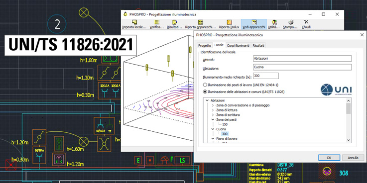
The PHOSPRO lighting calculation application, available in CADelet/Smart/iDEA/Eplus is now updated for verifying the lighting of domestic residential interiors according to the new UNI/TS 11826:2021 standard.
The technical specification provides prescriptions on the execution, operation and verification of artificial lighting systems in domestic residential interior environments, with the exclusion of environments and areas for which there are specific regulations.
After filling in the project data and the characteristics of the room to be illuminated, it is possible to identify the level of illumination expected for the various types of rooms and activities according to UNI EN 12464-1 standards for workplaces or UNI/TS 11826:2021 for home residential interior lighting.
If the lighting calculation function is started from Room management, for a room to which a specific type has been assigned (room, entrance, etc.), the software automatically sets the standard relating to residential rooms and, if possible, identifies the regulatory environment in the list more coherent, by setting the relative minimum illuminance level.
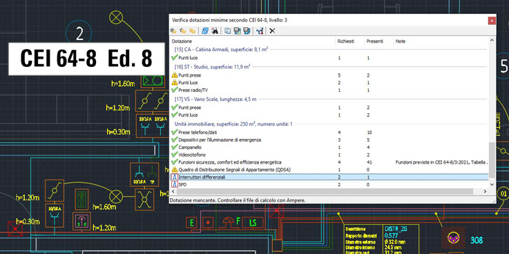
Updating of the typical equipment of the plant according to the classification of the new CEI 64-8 VIII ed.
The verification of the typical plant equipment according to the classification of the CEI 64-8 standard has been adapted to respond to the changes introduced by the VIII edition of the standard (chapter 37 of the standard). The adjustments introduced concern in particular the following points.
• The Anti-intrusion and Home automation equipment are included in the new Non-electrical functions equipment, verified for levels 2 and 3 (see Table A, note 14 of the standard).
• The STOA (Scatola di Terminazione Ottica d'Appartamento, Apartment Optical Termination Box) equipment is added, verified for level 1 only.
• The QDSA (Quadro di Distribuzione Segnali d’Appartamento, Apartment Signal Distribution Board) equipment is added, verified for levels 2 and 3.
See all new features 2023:


