New features 2025 Series - Electrical CAD
Electro Graphics releases the latest 2025 Series of electrical and photovoltaic design software. Here are the most important features and enhancements introduced in the electric CAD CADelet, iDEA, Eplus.
See all new features 2025:
Download brochure Electro Graphics New features 2025
Eplus and iDEA are based on the new AutoCAD OEM 2025 engine
One of the main novelties of the 2024 version of iDEA and Eplus is the update from version 2024 to version 2025 of the Autodesk AutoCAD® OEM engine on which the two electrical CADs are based.
This new version of CAD offers a set of advanced features and high performance to meet the needs of the most demanding professionals.
• AutoCAD OEM 2025 CAD engine: ensures maximum accuracy, reliability and compatibility with the latest CAD file formats.
• Increased performance: top speed and responsiveness for a smooth and uninterrupted workflow.
• Advanced tools: a wide range of functionality for 2D and 3D design, analysis and technical documentation.
• Customisable user interface: an ergonomic working environment adaptable to specific needs.
CADelet supports AutoCAD 2025
• CADelet line software is now compatible with AutoCAD version 2018 to 2025 64 bit.
• Smart line software is now compatible with AutoCAD LT version 2018 to 2019 64 bit.
Optimised access to symbol libraries and material archives on a remote network also on SQL databases
Symbol libraries and archive databases are crucial elements for the workflow within a company, guaranteeing the sharing of customised blocks and up-to-date archives. Version 2025 introduces an important innovation: the sharing of symbol library lists (standard and user catalogues) on servers with SQL databases, similarly to what is already provided for archives (materials, devices, cabling,...).
From version 2025, it is possible to use Microsoft SQL Server©, SQLite© and MySQL© technologies.
Sharing on servers with SQL databases allows faster and more efficient access to symbol libraries and material archives. Teams can collaborate more effectively on shared projects, always accessing the latest version of symbols and archives. Centralising data on servers with SQL databases ensures consistency and integrity of information, eliminating the risk of discrepancies between different local copies.
Definition of dynamic parametric macroblocks
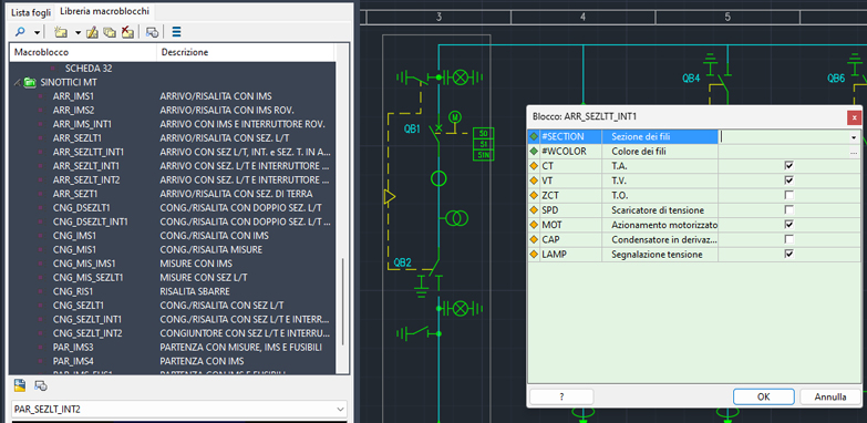
A macroblock is a set of graphic entities (symbols, electrical lines, wire leads, constraints, ...) inserted in the same sheet that can be saved (as a single dwg file) in the parametric macroblock library and reused in drawings. This is particularly useful when the circuit configuration represented by the macroblock is repeated several times within the same drawing or in different drawings. The features that distinguish parametric macroblocks from common macroblocks that can be stored in the symbol library are the presence of variables and the possibility of using them for the automatic generation of a circuit diagram using the Fast Builder tool, the automatic drawing of the Plc and the single-wire diagram.
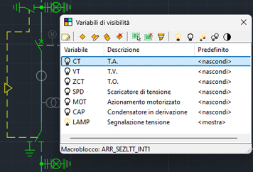
The use of the new visibility variables makes it possible to act on the visibility of macro-block elements dependent on diagram or system parameters. This function therefore makes it possible to define dynamic parametric macro-blocks.
Visibility of macroblock elements dependent on diagram or system parameters
The visibility of individual elements of a macroblock can now depend on diagram or system parameters.
Visibility variables in parametric macroblocks
In the 2025 version of the software, the Visibility Variables are a new type of parametric macroblock variables that, unlike the Text Variables, control the visibility status of one or more of the objects constituting the macroblock. This makes it possible to control, through the value of these particular variables, the graphic composition and circuit configuration of the macroblock without necessarily resorting to the use of graphic variables. Each individual graphic object belonging to the macroblock (line, text, symbol block,...) can be assigned to a single visibility variable. The value of this variable controls the visible/hidden status of all graphic objects with which it is associated.
Use of variables in text and multiline text inside macroblocks
The use of variables in parametric macroblocks is now also possible for text and multiline text objects in a manner completely analogous to what is already available for attributes in blocks.
It is possible to set a default value, which is assigned to the variable when the macroblock is inserted into the drawing from the Macroblock Library or when the macroblock is used in the automatic drawing of single-line diagrams and PLCs
PLC: I/O Chain Tracing with parametric macroblocks
The electrical diagram of the PLC I/O chain, i.e. the connections between a PLC and its input/output devices (I/O), can be drawn automatically in CADelet/Smart/iDEA, after having defined the PLC project within the PLC Management application.
It is now possible to draw this representation also using parametric macroblocks.
Parametric macroblocks with type of use = "PLC" are dedicated to use with PLCs; they include the symbol of the operand and the circuit diagram connected to it, ensuring a more flexible, fast and coherent representation of PLCs and their connections.
Using macroblocks, it is possible to quickly build the PLC electrical diagram in the drawing, even by manually inserting the macroblocks from the Library or building the drawing using Fast Builder, and then starting the reconstruction of the project from the PLC Management application. The data specific to the operand, in this type of representation, are added via the dedicated variables in the PLC type macroblocks, defined in a customizable profile.
Drawing of macroblocks assigned to operands and data synchronization between PLC project and drawing
The drawing of the macro blocks assigned to the operands and any updating of the macro block variables from the PLC project, or vice versa, the updating or reconstruction of the PLC project using the macro block data in the drawing, are carried out using the functions already available in PLC Management.
Unifilar MT using cells composed by parametric macro-blocks
Medium voltage (MV) cell synoptic diagrams are detailed graphical representations illustrating the arrangement and connection of components within a MV cell. These diagrams play a key role in the design, installation, maintenance and operation of medium voltage electrical systems. They provide a comprehensive visual representation of the cell's components, including circuit breakers, measurement transformers, busbars, cables and protective devices.
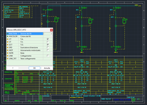
The automatic drawing of the single-wire diagram for medium-voltage panels, both in CADelet/Smart/iDEA/Eplus and in Ampère, can be completed by assigning the units of the MV cells the synoptic diagram representing their internal circuit. The assignment of these circuits can be done in Ampere, for each unit. The automatic drawing of the diagram guarantees the correct connection between all elements.
Note. In order to assign the synoptic diagrams to the units of the medium voltage cells, Ampère, Ampère Professional or Ampère Evolution must be included in the installed licence.
Assignment of synoptic diagrams for the single-wire diagram
The assignment of the synoptic diagrams to be shown in the single-wire diagram must be done in Ampere in the unit data window and only for units with an electrical system set to Medium or High Voltage.
In the protection system section it is possible to activate the MT/AT cell and access the MT Synoptics archive to choose the appropriate model.
Drawing of the single line and carpentry assigned to the MT cells
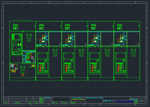
The automatic drawing of single-wire diagrams for MV panels, using synoptic symbols, also makes it possible to represent the carpentry assigned to MV cells.
The carpentry is automatically drawn in sheets following the single-wire diagram, according to the panel layout scale set in the project parameters.
Archive with typical MT cell types and assigned macroblocks, with preview
The MV Synoptics archive contains synoptic diagrams of typical types of medium-voltage cells, used for drawing single-wire diagrams of MV installations.
The synoptic diagrams consist of dedicated parametric macroblocks, which can be selected in the Macroblock Library in CADelet/Smart/iDEA/Eplus.
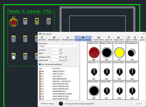
Quickly defining the layout of control panels and pushbuttons
A control panel is the control interface of a machine or system, grouping buttons, indicators, switches and other devices. Control panels are a special type of control panel with a flat surface and arranged buttons and indicators.
The new control panel drawing wizard simplifies and speeds up the creation of layouts for pushbuttons, pushbuttons and other control panels. This function generates the layout drawing automatically, placing the components in a grid predefined by the designer to ensure an orderly and precise layout. The software will then draw the layout in the current sheet.
Following the automatic drawing of the panel, it is possible to complete the representation with
• the table of materials constituting the panel itself;
• the automatic drawing of the drilling plate;
• the automatic drawing of the back panel connections.
The panel drawing function is available within the panel layout drawing window (DLAYOUT command).
Table of labels and drilling plates for control panels and pushbuttons
Following the representation of a control panel or button panel using the automatic layout and drawing function, the following related representations can also be added automatically. These representations can always be started from the layout composition window of the control panel.
Control panel material table
The panel material table provides a list of the devices that make up the panel drawn in the current sheet, with their identifying and descriptive data.
This function makes use of a dialogue box that allows the selection of the sequence of data to be included in the descriptive table as well as the choice of the table's graphical properties.
Table data can also be exported to a text or spreadsheet/Excel file.
Drilling plate
After drawing the layout of the control panel, with all luminaires, the software can automatically draw the layout of the drilling jigs for the components.
The drilling plate function requires you to select the panel layout, with all fixtures, i.e. two points that define the panel area. The software then proposes the drawing of the panel rectangle within which, for each of the shapes detected, the hole profile is drawn.
Back panel connections
After having drawn the layout of the button panel, it is possible to draw the representation of the contacts behind it via the function Back panel connections.
Nuova finestra interattiva e agganciabile di layout componenti su quadro
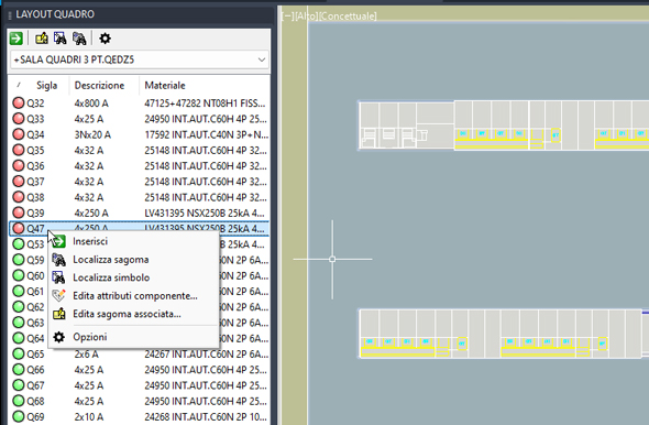
In CADelet/Smart/iDEA/Eplus 2025 a new interactive and dockable window for component layout on a panel is now available.
The PANEL LAYOUT pane can be placed aside to the drawing area so it keeps the work area clearer. This window shows the list of components belonging to a panel, a cabinet or a switchboard of the current diagram, and allows you to position the shapes in the drawing and execute panel layout management commands.
It can be detached and repositioned within the graphic area like the other dockable panels, by dragging the panel title.
The LAYOUT QUADRO panel offers a simplified interface for inserting panel shapes and docked to the work window keeps the work area clearer. You can thus interact with the layout on the diagram, move sheets, edit and delete equipment with the standard CAD functions.
At the top of the panel is the selection box with the locations found in the current diagram. When a location is chosen, the list is populated with the equipment and terminal blocks belonging to the selected location. The list is automatically updated in the event of component or drawing changes. Different icons, visible in the first column, represent the status of the component. These are the same icons used in the panel Layout window (full version) and visually give the status of the component already drawn or ready for drawing and the information compiled in it.
At the bottom of the panel is the component insertion mode selection box, which is used when starting the layout insertion command:
• Manual insertion
• Axial insertion
• Rail insertion
• Insertion on DIN rail block
The toolbar and context menu provides the most common commands for managing a layout.
Insert
The drawing of the shapes of the components selected in the list (use the SHIFT key to select multiple components) takes place after pressing the Insert button, which is also available in the right-click cursor menu. Otherwise, drag the elements into the drawing (Drag & Drop). The software prompts you to select points in the drawing depending on the insertion mode set. In the case of axial or rail insertion, an appropriate object snap facilitates component positioning.
Edit component attributes
Launches the attribute editing window on the component symbol in the circuit diagram. The command allows you to correct e.g. the component symbol, description, location or material code, without moving from the component layout sheet.
Edit assigned shape
To check or change the shape data of the assigned article (one or more).
Localise shape
If already inserted, it is possible to locate the shape of a component selected in the list of the LAYOUT panel: a zoom of the drawing is displayed where the shape is visible and marked with an arrow.
Localise symbol
To locate an equipment symbol in the circuit diagram.
Panel temperature verification with multiple cooling elements
The CADelet/Smart/iDEA/Eplus panel overtemperature calculation and verification function can also calculate and evaluate a cooling unit, if required.
To meet the need for several cooling elements within a panel room, the possibility of defining the number of elements (fans or air conditioners) with a direct effect on the calculation has been added.
The cooling or suction power specified in the overtemperature verification report is calculated taking into account the number of ventilation or air-conditioning elements specified in the panel design.
Marking of electrical equipment on the floor plan
The Plant Symbol Marking function is the tool that facilitates the marking of symbols in the plan sheet in CADelet/Smart/iDEA/Eplus.The mark assigned to the symbols is user-definable and is generated by the combination of user-defined data in the marking profile. The order of addressing and the resulting index in the acronym is based on the sequential order in which the user selects the symbols.
Customisable options in the marking function make it possible to activate unique marking for all symbols in the plan drawing, and the marking constraint to prevent subsequent modification of the marking by the marking commands.
Export and import to OpenOffice (LibreOffice) Calc©
Several functions in Electro Graphics software allow data to be imported or exported by interfacing with a spreadsheet. In CADelet/Smart/iDEA/Eplus, for example with Fast Builder, Vario, Load Analysis, PLC Management, all plant or material tables, but also in Ampère for unit data, in Cablo for the cable list, Tabula and dictionary archives.
The import or export window proposes the different ways in which the software can import or export data. The following options are available.
• Microsoft Excel©: this mode can be chosen if Microsoft Excel is installed on the system. For export, the Electro Graphics software automatically starts the Excel software and exports the data directly to a new spreadsheet. Changes can then be made or the file saved. For import, on the other hand, the Electro Graphics software copies the data from the spreadsheet currently open in Excel.
• Spreadsheet (*.xls, *.xlsx): This mode is useful when Microsoft Excel is not installed on the system. For export, an Excel file is created in .XLS format and saved to the path with the name specified by the user. For import, a window is opened for selecting a file in .XLS format.
Version 2025 provides a new mode.
• OpenOffice (LibreOffice) Calc©: It is possible to choose this mode if OpenOffice (LibreOffice) Calc© is installed on the system. In a similar mode to Microsoft Excel©, the system automatically starts the software and exports the data directly into a new spreadsheet. Changes can then be made or the file saved. For import, however, Calc must already be started and the Electro Graphics software copies the data from the currently open spreadsheet.
See all new features 2025:
Download brochure Electro Graphics New features 2025


