New features 2023 Series - Electrical grid calculation
Electro Graphics releases the latest 2023 Series of electrical and photovoltaic design software. Here are the most important features and enhancements introduced about Electrical grid calculation in the software Ampère line and EGlink.
See all new features 2023:
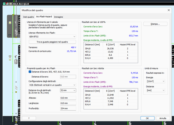
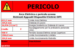
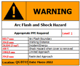
Arc Flash analysis of the switchboards according to the IEEE 1584-2018 standard with printing of the report and the signaling label to be affixed to the switchboard
Electrical systems must minimize and mitigate the effects of electric arcs, especially if generated by live work, due to short circuits accidentally triggered by operators near live electrical parts. In industrial environments, currents or voltages fault can create explosive electric arcs, with the release of molten material and dangerous radiation.
Ampère 2023 analyzes the danger level of the electric arc that can occur in an electrical panel, defined by the incident energy value calculated at the working distance. The incident energy determines the level of protection of the PPE personal protective equipment that personnel in charge of live activities must wear. Other risk mitigation initiatives concern the choice of suitable equipment and systems, such as circuit breakers with fault current limitation and Arc Flash light sensors designed to quickly interrupt the power supply.
Ampère applies the calculation models provided by the IEEE std 1584-2018 standard for the determination of the incident energy (E) and the Arc flash limit (AFB) as defined by the NFPA 70E standard.
The software tool for calculating the incident energy inside switchboards also allows you to print the results of the calculations performed by applying the IEEE 1584 standard, mainly to create labels warning of the danger of electric arcs to be applied on the switchboard fronts.
The Ampère software provides some templates and gives you the ability to create your own templates in the template manager.
Protections with AFDD arc flash mitigation device as an auxiliary element
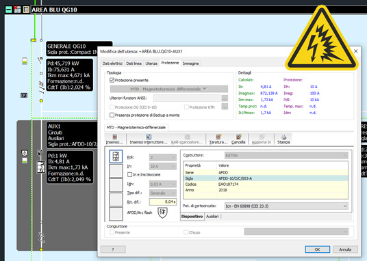
Ampère now allows you to manage protections with the AFDD characteristic. The detection function is normally assigned to an electronic system inserted in the protection which guarantees the intervention. Therefore the protections in question are marked as AFDD/Arc flash.
The Devices archive window allows a quick search for AFDD protections thanks to the filter available in the Find box. Inside the grid, the Status column shows the AFDD property of the protections with the appropriate shield symbol for easier identification, as also occurs in the mesh.
Tabular multiple editing of the units, with rapid addition of typical units
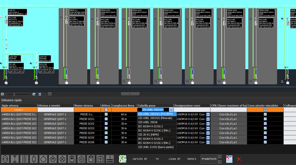
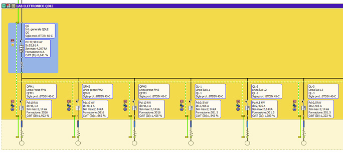
The new Quick Edit panel provides a quick method of managing and editing data for one or more drives; allows multiple modification of the parameters shown in the table, thus making it easier and faster to operate simultaneously on similar users, make modifications and change configurations. The panel may or may not appear depending on your usage. The table shows the units selected in mesh arranging them by rows. The columns, on the other hand, show the data of interest according to the chosen display profile.
It is possible to define different display profiles. Having several profiles, it is possible to select the one of interest on the toolbar at the bottom. Depending on the selected profile, different columns are then displayed which, depending on the data, allow the editing or selection of an option.
The Quick Edit panel also has a toolbar that allows the insertion of predefined typical units (transformer, distribution with cable, etc.). This facilitates the composition of the mesh, leaving the development of all the other parameters characterizing a user to a later stage. The connection of the new users takes place in cascade with respect to the initial user selected. By selecting a different row of the unit table in Quick Editing, it is possible to change the reference user, and therefore the origin of new users. With this system, the designer can quickly compose more or less complex parts of a system, leaving the specification of the data to a later stage.
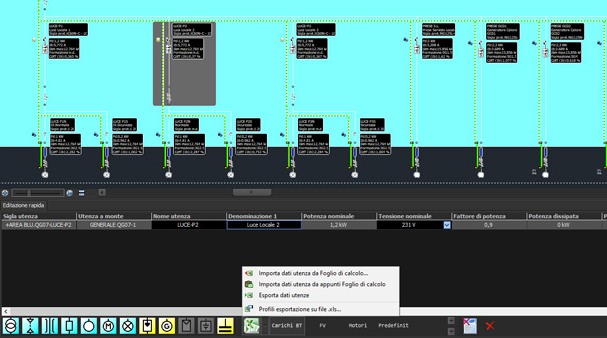
The Quick Editing panel also contains the commands for exporting data to Excel or a spreadsheet, with the possibility of creating complete and highly customizable reports. Therefore the new panel can be used as a link between the mesh and the spreadsheet for quick and/or multiple modification operations of more information.
Multiple and filtered search and replacement of cables and protections
The new version of the Ampère line offers the new Find and replace cables function and an update of the Find and replace protections function.
Find and replace cables
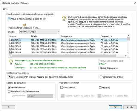
If you need to replace one cable with another, the new cable replacement function is now available; just select the user with the cable to be replaced in the knitting and start the command. A dialog window lists all the users with the same cable (make and model) as the first one selected. If necessary, there is a filter tool that restricts the search to only the cables belonging to a given panel. The new cable will be associated with all users in the list.
Find and replace protectors
The function to replace the protectors has also been updated in line with the new cable replacement function. This is useful when you have to change a protection with another model because, for example, it is no longer available on the market and replaced with a new product.
New management of the combined type protections with the possibility of coupling release and circuit-breaker of different manufacturers.
Composite types
Ampère has a new protection management, it is possible to compose up to 4 distinct elements and a greater number of predefined combinations is available.
A unit can contain multiple protection elements in series, limiting the need to create multiple users to complete what is required.
The initial list shows all the selectable basic types managed by the software. With a click of the mouse you can select the type and then assign a material code by querying the Devices archive.
Many basic types are also the first element of one or more compositions, displayed by scrolling the mouse pointer over the corresponding cells.
The classic MT+D composition means the residual current device as a secondary element in series with the circuit breaker. Although in most cases the residual current device is a relay to be combined with the magneto-thermic, the software leaves the freedom to be able to assign even a pure residual current device with its own release device. The choice is made using either the Insert command (pure differential) or the Release relay command (relay differential).
Interconnectable elements
It is now possible to associate a coupled element belonging to a manufacturer different from the reference one to a starting protection. In addition, the list of types of protection that can be chosen as a coupled component has been expanded. The list now includes the residual current, relay release, magnetic, thermal, fuse types.
Possibility of setting positive and negative adjustment tolerances
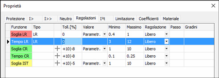
The management of the tripping tolerances for the electronic protections has been further improved. The error committed by the trigger protection can now be both positive and negative and with different values. The negative value can be added in the same column reserved for the adjustment tolerance, using a string like +10|-8.
Generation of typical protection reports and collation of the data sheet in the project documentation
The list of print attachments increases with the Protection characteristics print, which shows a table with the characteristics of the protections present in the project.
It can be useful for providing the fitter with the most important information on the protections when the manufacturers' reference catalogs are not available, obtaining the information directly from the Devices and Materials archives.
Print of cable summary, multi-core or single-core, by type
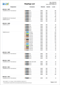
The list of print attachments is enhanced with the Cable summary printout, which provides the list of cables used in the project and the total quantity in metres. It can be useful for compiling purchase estimates, knowing how many meters of each cable are needed for the project.
The list of cables is sorted by type (multi-pole/single-pole), designation and formation. Optionally, the cable list can be divided by Zone or Panel where the cable is installed.
Automatic filiation for protection backups, at multiple levels
In the new version of Ampère Professional, the automatic search functions for units with protections that can be coordinated in backup have been further developed.
The search for upstream protection occurs at up to five levels. When a backup relationship is available between the protection of the unit in question and an upstream one, the software shows the possible coordination in the Advanced Backup Features panel. Then, you can confirm the backup relationship.
To speed up the assignment and management of the already assigned backup relationships, it is possible to take advantage of a command which allows one or more proposed coordinations to be assigned; in the same way it is possible to eliminate one or more coordinations present.
Commands are also available which allow you to assign all the relations proposed in the list at the same time or to cancel those already assigned.
Identification of elements in the field, even in single-line diagrams
The units, made up of protections and ducts, are always assigned to a switchboard, but this can be the physical container, or the logical container they belong to, i.e. the switchboard from which the unit derives.
Ampère 2023 allows you to better detail this difference by highlighting the units with only protections and physically installed inside a panel. Pipes, on the other hand, now determine the outer boundary. Downstream of them, the units, even if assigned to the same switchboard, are considered physically external to the switchboard and therefore called elements in the field.
The new display mode of the mesh, called "Highlight internal panel" visually groups the units by panels, adding the distinction between internal units and external ones. For each picture, the colored part represents the internal part, while the hatched and colorless area marks the part in the field.
In any case, if the designer needs to size stretches of cable or busbars inside a switchboard, he can do so by assigning the Conduit inside the switchboard to the units: consequently the protections connected downstream remain physically inside the switchboard.
Protections and pipelines defined as elements in the field influence the functionalities which, in their calculation or representation, consider the contribution of a set of elements. Think of the panel overtemperature: it considers the dissipation of all the elements inside the panel such as protections, cables and other devices.
From the 2023 version of the Ampère software, the elements in the field will be excluded when calculating the panel overtemperature, obtaining a more precise value.
The new Arc-flash functionality analyzes critical points of failure within an enclosure.
In the Print user diagram, the logic of belonging to a panel can be activated thanks to the property Tracing limited to outgoing cables. In this way, the units will be drawn up to the on-board pipes, similar to the representation in mesh.
Vector analysis of fault current flows, symmetrical and asymmetrical
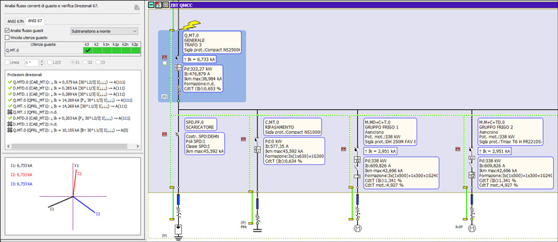
Ampère Professional 2023 uses a brand new algorithm to calculate the current flows that feed a fault, allowing you to study the directions and quantities involved. It is therefore possible to analyse:
• the fault currents "seen" by the protections involved in the fault;
• the behavior of the directional phase protections 67, and set up their settings;
• the cumulative contribution of the magnetizing current, called in-rush, for several transformers seen from a protection;
• the contribution to failure of the electric motors present in the network;
• the propagation in the network of an asymmetrical fault in the presence of star-delta transformers.
Analysis of the fault currents passing through a point due to a fault in another set point
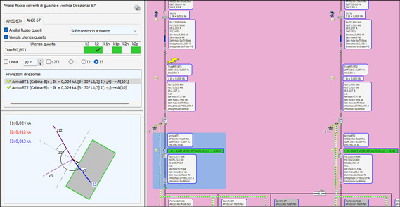
The new fault analysis function displays the current flows directly in the loop, reporting values and directions.
It allows you to understand the sources of the fault at a glance and therefore highlights the contribution of the motors and generators which add up to the value of the network supply.
It also improves the selectivity analysis between two protections found in electrical networks that have parts connected in parallel or in a ring, therefore more complicated structures than the typical radial scheme.
The new selectivity analysis window is set up to automatically manage this situation when two users are selected, displaying the fault currents of a reference user and the fault currents seen by the user upstream.
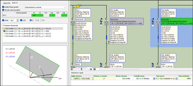
Fault analysis with 67 phase directional protections, in order to determine direction, characteristic angle and tripping logic
The new version of Ampère now also manages the ANSI 67 function, Directional phase overcurrent.
The designer will be able to analyze the behavior of the protection following various types of fault and program the protection by adjusting the Direction, Characteristic angle and Tripping logic settings.
The report on the study of directional protections 67, compiled by Ampère Professional, can be attached to the printouts of the project. The printout shows the complete analysis in the three current phases together with the final result.
Check selectivity for fixed fault point with in-rush transformers in parallel
When two or more transformers are active at the same time, they draw magnetizing currents which add up along the common power supply lines, stressing the protections more, with the risk of opening due to overcurrent.
The risk of opening is the problem to check, and also in this particular case the new selectivity analysis window is designed to best verify this problem. By choosing one protection and more than one transformer, the software proposes the total magnetizing current seen by the protection.
Contribution of motors during a fault
Ampère has always calculated the contribution, during a breakdown, of motors, generators, storage systems, etc. Therefore the fault current in a point can be the sum of various elements, each with its own 'weight'.
The Fault analysis function allows you to view the current flows and understand the sources of the fault at a glance. In particular, choosing the first unit connected to the supply as the fault point, it shows the contribution of the motors and generators, a value coinciding with that reported in the Supply under the name Contribution of the plant to the grid short-circuit current.
Asymmetric faults
The analysis of fault currents is also useful for studying asymmetrical faults and the currents seen by protections positioned on the opposite side of a transformer.
Definition of condition of logic selectivity between protections
The new version of the Ampère software allows you to specify when two protections are in logical selectivity between them. This coordination allows the connection of the switches, which in the event of a short-circuit quickly isolate the fault area, isolating the plant only at the level closest to the fault in particularly short times, keeping the rest of the plant operational.
The function is particularly useful in ring and grid systems, where, in addition to the zone, it is also essential to define the direction of the power flow, which feeds the fault.
Logic selectivity is also highlighted in the time-current tripping curves window.
Lists of preferred manufacturers, with dedicated filter in all archive access operations
In the configuration parameters associated with the project job it is now possible to set the profile of the active manufacturers.
The assignment of a profile of active manufacturers influences the display and search filters in the archives. This means that when you have to select a protection equipment or a cable, photovoltaic module, an inverter or in any case even just the article code of one of the components for the system, only the elements relating to the manufacturers enabled by the active profile will be displayed for the choice.
It is also possible to temporarily ignore the active profile to allow particular searches.
EGlink: BIM integration between Revit© MEP and Ampère Professional
EGlink is an interchange plug-in between Autodesk Revit and Ampére Professional and represents the Electro Graphics's response to BIM (Building Information Modeling) process mode. Here are the most important features and enhancements introduced in EGlink 2023.
Function extension and update to Revit 2022 / 2023
EGlink is now compatible with Revit MEP 2017, Revit 2018, 2019, 2020, 2021, 2022 and Revit 2023.
Optimized management of further parameters and recognition of typical electrical quantities
New descriptive parameters and electrical sizing values of units now available in Revit.
Recognition of non-electrical connection elements such as manholes or similar, for the purpose of routing users
The routing of cables inside cable trays and electrical pipes with EGLink 2023 is now not interrupted by any elements of type "Electrical equipment" even if these families do not contain any electrical connectors.
All elements of the type "Electrical equipment" are therefore now interpreted as duct junction elements. The presence of the electrical connector is no longer discriminating.
This is the case of sumps or similar connection elements which interrupt the cable carrying elements but must not interrupt the routing of the circuits.
See all new features 2023:


