

electroBIM New
Designing electrical distribution systems in BIM environment
electroBIM is a plug-in for Autodesk Revit® developed by Electro Graphics to support the design of electrical distribution systems in a BIM environment.
- Autodesk Revit® rel. 2018 to 2024 required

electroBIM is a plug-in for Autodesk Revit®, developed by Electro Graphics to support the design of electrical distribution systems in a BIM environment. The software enables the management of ducts and conduits based on a library of common products and associates relevant information with Revit tracking functions for 3D modeling of cable routes according to the chosen product. A dedicated manager allows for the definition of electrical utilities, supported by a navigator that simplifies and speeds up access to typical data (voltage, power, current, power factor, cable type, and installation method). The automatic cable routing function connects various elements of the system to distribution panels and determines optimal paths along modeled backbones. Power propagation to various levels of the system determines conductor sizes based on cable types and installation methods correlated with the paths taken, coordinates with anticipated protections, and calculates voltage drops at every point in the system. Lastly, the filling status of passageways, whether they are pipes, ducts, or walkways, is managed; annotative elements are available to display all information on the status of conduits.
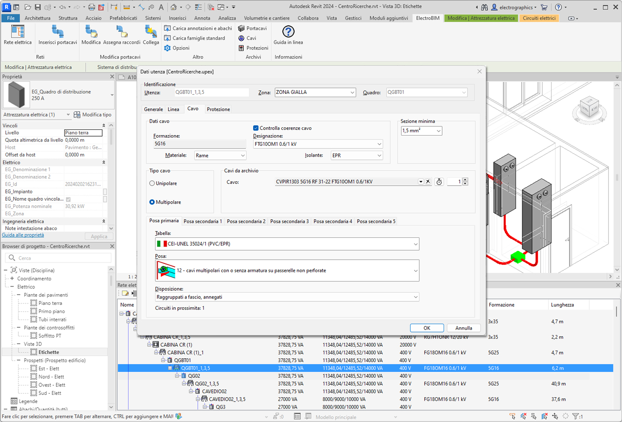
Definition of electrical utilities
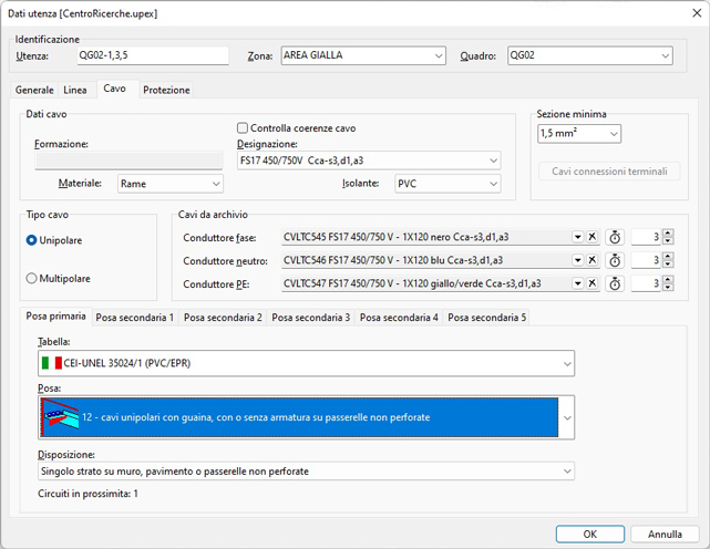
After defining electrical equipment in Revit, the electrical network manager allows editing of each element within it, whether it's a load or a distribution panel, assigning descriptive data and associating it with a specific zone and panel. Typical data such as power rating, power factor, electrical system, ambient temperature, number of poles, and type of expected protection can be assigned, as well as managing laying tables CEI-UNEL 35024/1 - 35024/2 - 35026, IEC 364 (1983), IEC 60364-5-52, IEC 448, and IEC 61892-4. Operators can also directly assign cables and protections, automatically selected from their respective database, which contain over 100,000 elements.
Labeling of electrical equipment
Labeling of all electrical elements is provided, with the ability to set the name for each component type, separator characters, and an incremental numerical index. Among the managed properties for electrical equipment, there is a constraint on the assigned label, which will not be changed by automatic labeling.
Archive of ducts, cables, and protections
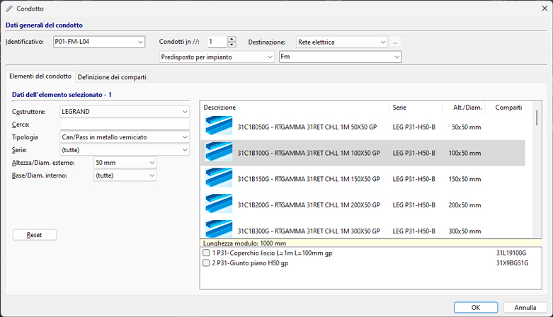
There are over 6,000 types of ducts or pipes available, sourced from leading manufacturers such as ABB, Gewiss, Inset, and Legrand. Each element is characterized by geometric and commercial parameters that uniquely drive the tracing of the 3D model expected in Revit for the corresponding system families chosen. The cable archive includes over 11,000 elements, with technical data related to cable type, sections, weights, bending radii, and conductor identification. The protection archive comprises over 90,000 elements of all types, selected from the major market manufacturers. All archives can be freely extended and enhanced by the operator.
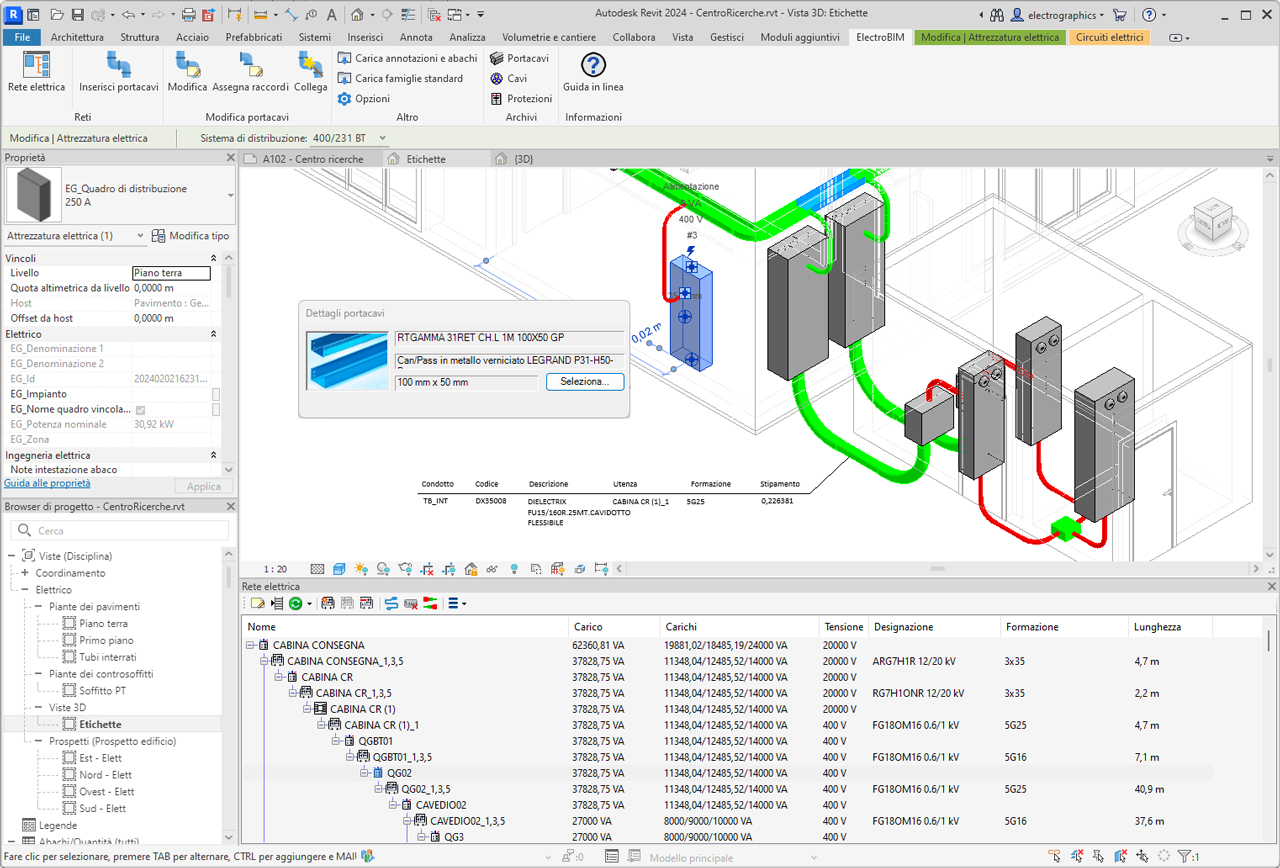
Drawing of 3D model
The software allows you to choose, from the available archives, the type of pipe or conduit to use using search criteria by manufacturer and type. This enables precise characterization of the system families that will be used during the design of the conduits with standard Revit commands. Thus, the 3D model of the distribution system will be the actual representation of the commercial product chosen for the development of the grid of connections in the electrical system.
Power circuit network generation
The electroBIM network manager retrieves all available electrical information from the families used in the project. These families model both distribution elements, such as panels and transformers, and terminal elements, such as outlets, lights, and other electrical equipment, within the electrical system designed in Revit, following the logic of defining power circuits. Simple and effective methods are proposed to associate loads with circuits and connect them to panels or power sources directly from the network navigator. It is possible to combine multiple electrical loads and manage them as a single element, simplifying network management. Each electrical data is linked to an Electro Graphics project parameter, which is visible in the Revit Properties palette.
Electrical network navigation
The electrical network navigator allows for quick and productive access to all electrical element data, as well as rapid editing with immediate localization in the Revit model. Practical functions are available for creating electrical circuits, assigning elements to them, or removing elements from already defined circuits.
Power propagation and protection coordination
The system handles power propagation across various levels of the system, taking into account use and concurrentcy coefficients defined for network loads. Similarly, it calculates the correct coordination between the operating current and the nominal current of the protection device, if present.
Automatic cable routing
The software provides functions for automatic cable routing, allowing the operator to adjust the paths of electrical cables according to specific needs if the shortest path identified by the software does not meet user preferences. It is possible to exclude certain loads from the route or set criteria that force cables to pass through specific points in the conduit system. The system automatically searches for the optimal path in the conduit network, taking into account exclusion or mandatory passage options, and provides:
• Accurate estimation of the length of connection cables.
• Number of nearby circuits, i.e., the maximum number of cables sharing the same conduit, for correct capacity calculations.
• Preliminary assignment of a specific installation for the utility, taking into account whether the circuit passes through channels, cableways, or pipelines.
Conductor size calculation
Based on the applicable standard, cable and conductor type, installation conditions, number of nearby conductors, and temperature, the software calculates the conductor size and then allows the selection of the cable from the database, thereby providing all weight and size information for a proper check of cable tray capacity.
Voltage drop calculation
electroBIM calculates the voltage drop at every point of the electrical network using an analytical method, considering electrical quantities in vector form. This ensures a precise and detailed evaluation of this parameter, which is fundamental in the design of the system.
Cable annotations
At the end of the plant design, the operator can extract calculated cable designations and specifications and display them in the Revit model using Electro Graphics' custom annotations. Annotations can be added to cable routes, including data from utilities along various sections and indicating the fill coefficient.
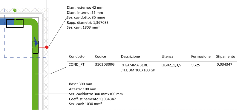
Cable duct filling checks
The network calculation also determines the cable fill sections and the filling level in the ducts; this data is reported in the Revit model through annotative elements, and it's also visually highlighted in the 3D view.
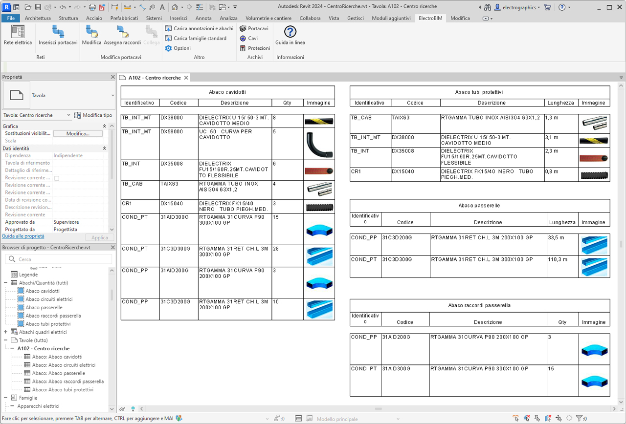
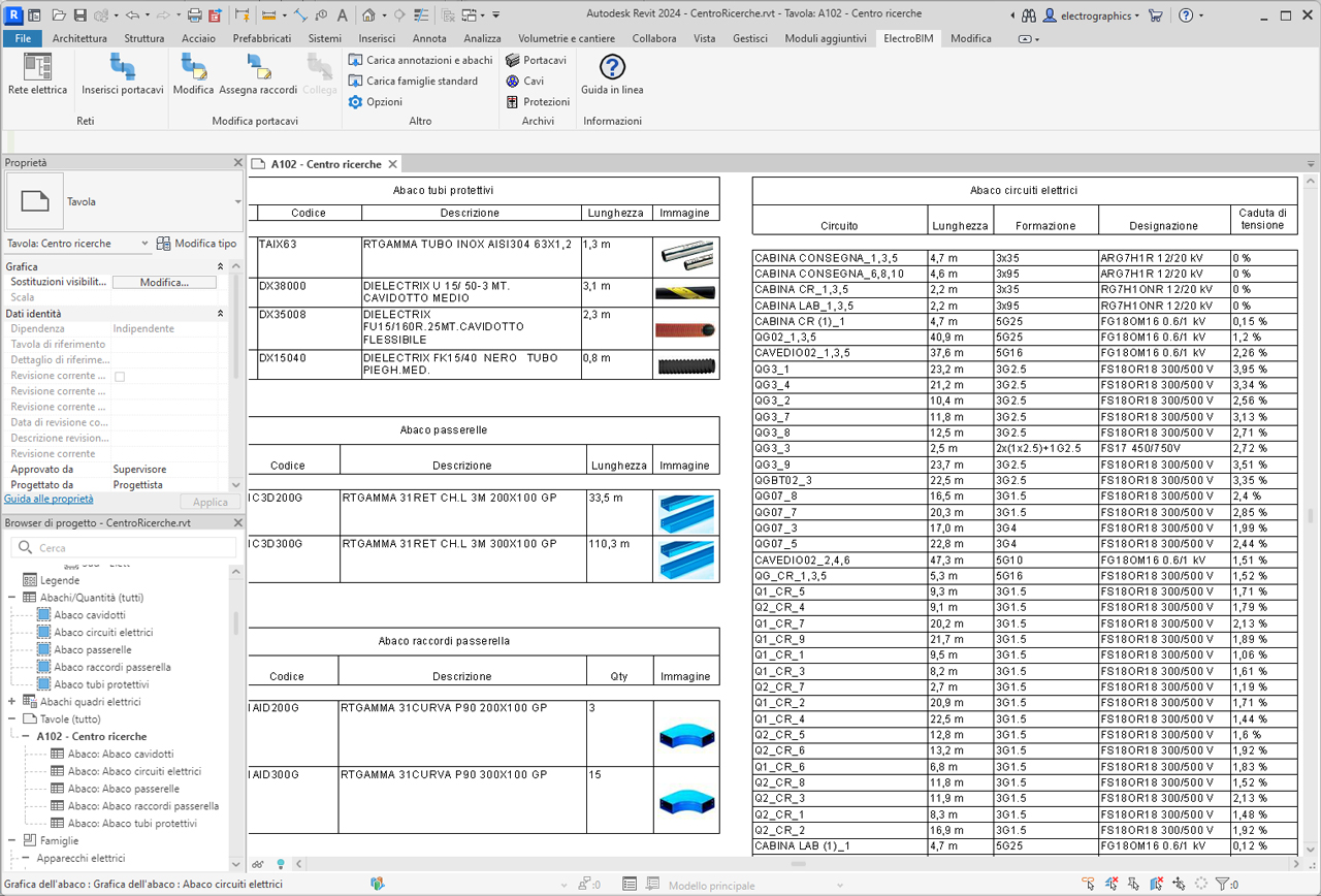
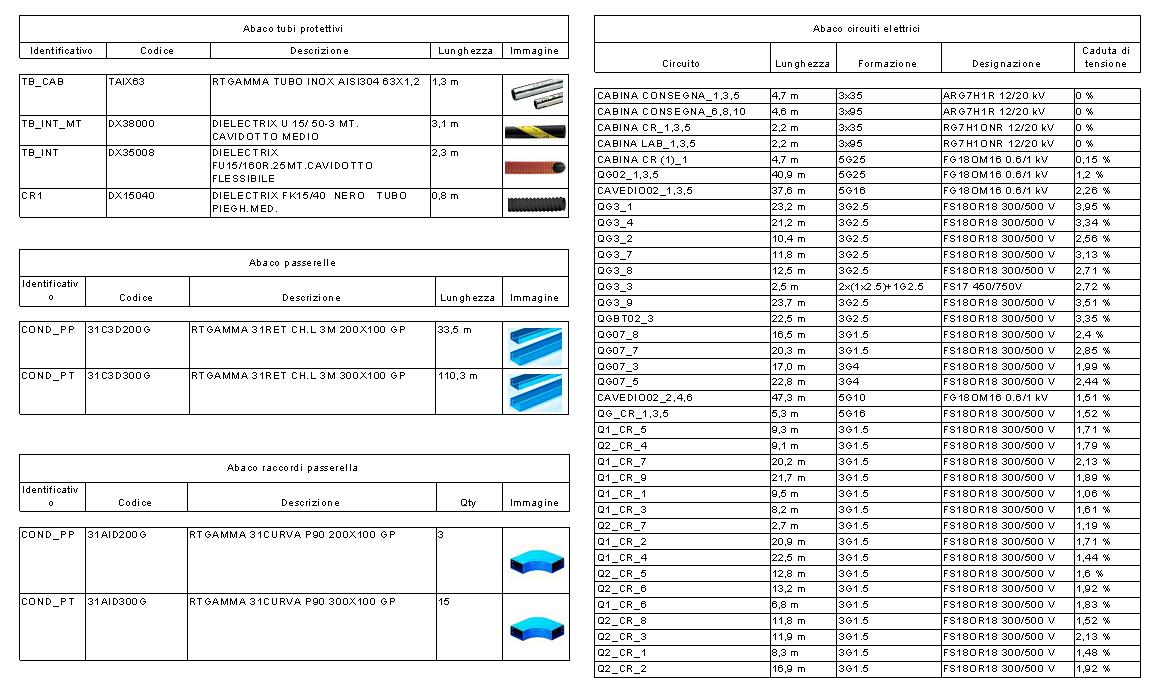
Abacus for cable ducts and electrical circuits
electroBIM makes available a series of preconfigured abacus families with fundamental electrical parameters, such as voltage, power, and current, and they can be customized to suit the specific requirements of the project. Through these abacus, it's possible to clearly visualize information regarding electrical circuits, including connected devices, load characteristics, and other relevant details. Abacus facilitate the creation of legends and technical documentation, providing a comprehensive overview of the electrical specifications of the project, essential for the proper development and maintenance of electrical systems.
Interoperability with Ampère line calculation software
electroBIM facilitates the exchange of data from the electrical network defined in Autodesk Revit© with the Ampère line calculation software, as an integral part of the BIM philosophy. This enables the sharing of information to ensure simple communication and collaboration among the various professionals involved in the project, as well as in the construction and maintenance of the building throughout its entire lifecycle. The automatic data synchronization mechanism of the network allows for a bidirectional connection between the project created in Revit and its representation in the computing environment. electroBIM leverages the capabilities of Electro Graphics' calculation software and transfers the results of the computations into Revit following a logic of data exchange, where utilities and their interconnections are bound by the network defined in the BIM environment.
System requirements
Minimum system requirements to install and use electroBIM.
- Computer with 3 GHz o higher processor.
- At least 8 GB RAM.
- Hard disk with at least 10 GB free space.
- Colour video and graphics board (SVGA or higher).
- USB, mouse, printer or plotter.
- Windows 10 (version 1809 or higher) or 11.
- Autodesk© - Revit© version 2018-2024.
ElectroBIM is a plug-in for Autodesk Revit®. It is developed by Electro Graphics to support the design of electrical distribution systems in a BIM environment. After installation, ElectroBIM is loaded and accessible from the Autodesk Revit ribbon installed on the PC.
See also
The following Electro Graphics software products connect to electroBIM to complete the list of all the tools needed for a complete professional electrical engineering.


News


