New features 2022 Series - Electrical CAD
Electro Graphics releases the latest 2022 Series of electrical and photovoltaic design software. Here are the most important features and enhancements introduced in the electric CAD CADelet, iDEA, Eplus.
See all new features 2022:
Eplus and iDEA are based on the new AutoCAD OEM 2021 engine
Among the main innovations of the 2021 version of iDEA and Eplus 64-bit is the transition from the 2018 to 2020 version of the Autodesk AutoCAD® OEM engine which the two electrical CADs are based on.
• Improve graphics performance, pan and zoom speed in 2D.
• Improved the quality of the PDF files produced, with size optimization.
CADelet compatible with AutoCAD 2022
• The CADelet line software is now compatible with AutoCAD version 2010 to 2021 at 32 bit or 64 bit.
• The Smart line software is now compatible with AutoCAD LT version 2010 to 2019 at 32-bit or 64-bit.
New user interface in the job order and project configurations manager
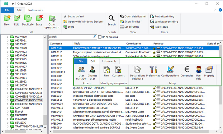
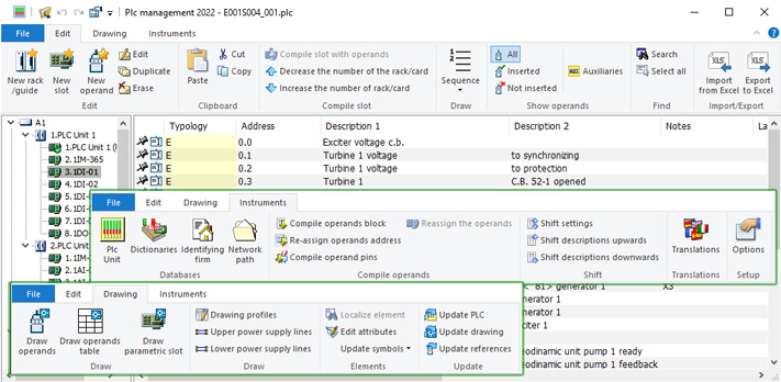
• In the new version of the Orders application, the command bars have been replaced with the ribbon bars with the typical style of the latest versions of the Windows operating system. The distribution of commands in group tabs allows you to have all the features available in a single command bar, with descriptions displayed and grouped by topics.
The procedures for quickly recalling the operating tools of the diagram have been extended and standardized
• Symbol library and other operating windows are minimized to allow the operation on drawing and be reopened quickly to continue the work.
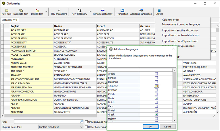
Completely new translation and dictionary management
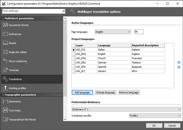
• Language configuration saved for each project.
• Definition and management of an unlimited number of dictionaries.
• Revision of the structure of dictionaries with extension of managed languages.
• Management of non-western languages on all customizable documents.
• Symbol legends, sheet list and material tables with bilingual description.
Descriptive markers of row or column functionality
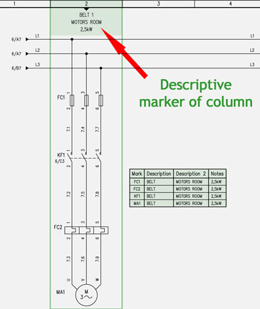
• The descriptive markers of the row and column features introduce the possibility of assigning one or more descriptive rows to the columns and rows of a schematic sheet.
• The descriptive texts are automatically assigned to the symbols inserted in the row or column where the marker is present.
• Markers are blocks with fully customizable graphics.
Improvement and simplification of the management of wire returns
• The dialog box for inserting wire returns is now pre-filled by the software with the data most compatible with the circuit situation at the points selected for inserting wire returns.
New properties in the customization of wire numbering
• New parameters to customize the composition of parametric wire constraints and wire numbering.
• The new parameters refer to the Location and Function of the sheet in which the constraint is inserted.
Extension of the attributes that can be defined by the operator and their consistent management in all the documents generated in the diagram
• Additional custom attributes, in addition to those normally managed in each symbol.
• Custom attributes can be used as additional data in:
- Symbol list table
- Board layout summary table
- Custom material tables
- PLC operand table
New terminal management functions in the various phases of insertion on the diagram
• The new command for Change current sheet during insertion of terminals and connectors in the drawing facilitates the navigation of the diagram pages without the need to terminate the command in progress.
• Saving of terminal insertion options for each terminal block.
• Multi-level terminal insertion with free group, useful when pin numbering is used in the "group.level" mode in a terminal block where single terminals with multi-level terminals coexist.
New functions in PLC Management
• New PLC user interface using ribbon bar.
• Parameter profiling in the export of PLC data to a spreadsheet.
• New settings for concentrated drawing of PLC cards.
• Improved location and function management on boards and racks.
• Tables of the connection of the operands with the external actuators.
• Drawing connections with parametric constraint.
Attribution of Area and Plant information to the elements of the topographic diagram
• It is now possible to assign the Area and System information to the elements of the topographic diagram in order to then divide the elements of the electrical system by organizing them by Area and System.
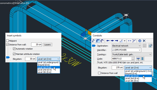
Definition of the elevation levels of the work planes of a project
• Simplification of the representation of the electrical system of a multi-storey building by drawing on the same floor plan in 3D.
• The elevation levels of the work plans define, in each project, the floors of the building.
• The level can be chosen for:
- 3D drawing of the cable ducts;
- the positioning of the symbols;
- the positioning of the compositions of fruit boxes.
New points of reference in the drawing of cable-conduits systems
• Possibility of choosing the work plan among those defined in the project.
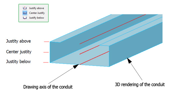
• Specify the conduit justification (Top / Center / Bottom) as a reference to refine the 3D rendering.
Diversified graphic representation linked to the type of cable conduit with summary legend
• Specific graphic characteristics (LINE TYPE) can be assigned to each type of cable conduit.
• Summary key of LINE TYPE to identify, in the plan, the different types of ducts.
Generic auxiliary networks, TV / SAT networks and machine wiring
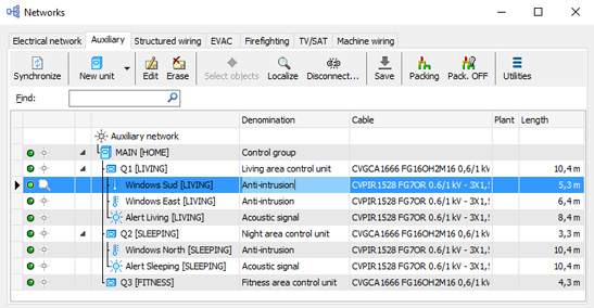
• New function of defining generic auxiliary networks to facilitate the laying of cables for auxiliary systems to the electrical system, as well as the home automation system.
• The following types of units are provided for the auxiliary network: Panel, Control unit, Concentrator, Sensor, Command, Signaling, Actuator.
• Definition of networks, independent within the system project, for the automatic laying of TV and SATELLITE TV cables.
• Definition of the set of active and passive electronic devices, control units, amplifiers, sockets, designed for the distribution of the TV signal in the various system modes envisaged.
• The TV / SAT network can also be developed within the Networks interface according to the structured cabling method.
• The Networks - Cables diagram interface is now named Machine wiring and is reserved for inserting the cables defined in the circuit part of the wiring diagram, in the cable ducts defined in a plant layout such as the 3D of a machine tool.
Data network: definition of patch panels and ports for distributors and data network sockets
• In managing a data network (structured cabling), the data network distributor now allows you to define the number of data ports for each patch panel (disconnector of connections).
• Each terminal port defines the incremental number of patch panels and the incremental port number.
• All data are shown in the summary tables.
Management of the new format of the Ampère project file
• CADelet / iDEA / Eplus manage the new Ampère project file format, optimized and shared with all plant engineering functions.
Customization of the summary tables (list of symbols, cable holders, cables) on the active elements of the current AutoCAD layout window
Visibility of summary tables linked to the state of the current AutoCAD layout
See all new features 2022:


