New features 2021 Series - Electrical CAD
Electro Graphics releases the latest 2021 Series of electrical and photovoltaic design software. Here are the most important features and enhancements introduced in the electric CAD CADelet, iDEA, Eplus.
See all new features 2021:
iDEA and Eplus with AutoCAD OEM 2020 engine
Among the main innovations of the 2021 version of iDEA and Eplus 64-bit is the transition from the 2018 to 2020 version of the Autodesk AutoCAD® OEM engine which the two electrical CADs are based on.
CADelet compatible with AutoCAD 2021
The CADelet line products are now compatible with AutoCAD products from version 2010 to 2021 at 32 bit or 64 bit.
Power flow analysis on the wiring diagram
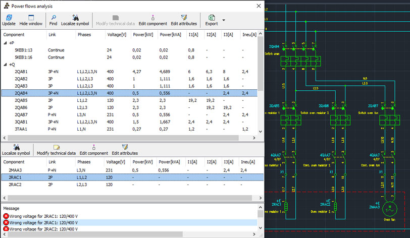
The analysis of the power flows is a function of CADelet / iDEA / Eplus software which allows to determine the power and current values required in certain points of the wiring diagram in order to allow the correct sizing of disconnecting and protection elements. power supply groups, generators, transformers and converters.
The analysis is aimed at two functions.
• Calculate the electrical power (active and apparent) absorbed by the loads connected to a component in the wiring diagram. The value of the absorbed power is acquired from the technical data of the material item assigned to the symbol in the wiring diagram.
• Calculate the current values on the component output lines. This second analysis depends on the definition of the phases on the symbol pins.
All analysis data can be saved on excel file.
Marking of symbols according to EN 81346-2:2020
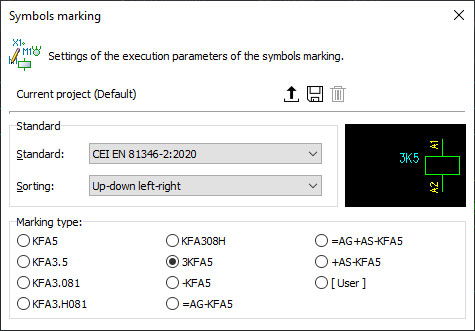
It is now possible to specify, for each symbol in the library, the marking family according to CEI EN 81346-2: 2020 in force from 01/01/2020, in addition to the previous CEI EN 81346-2: 2012.
The new standard, in addition to modifying or replacing some definition classes provided by the previous version, provides for a third subclass level, with three characters, further detailing the identification of symbols in the wiring diagram.
To set the family, similar to the previous standard, access the symbol setup window in the Symbols library and select the family corresponding to the “Family (CEI EN 81346-2: 2020)” value.
QR code in drawing and documents
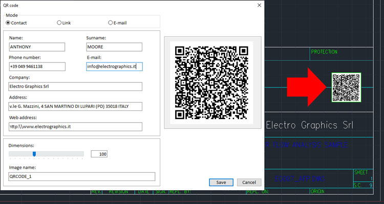
The QR code of the company associated with the project, or the materials used, can be inserted in the drawing and in material lists.
Connection marking
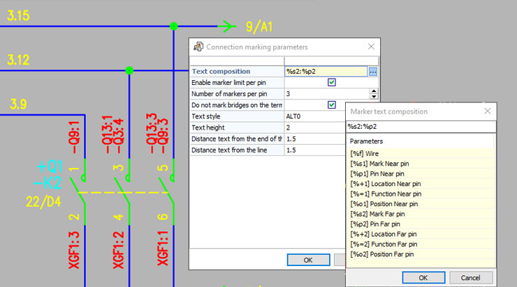
The new Marking Connected Wires feature allows you to write a variety of connection information near the symbol pins.
The information shown can be chosen, among those available, using the Connection marking parameters function, where it is also possible to modify the graphic properties of the marking.
The new function Insert wire markers allows you to insert in any point of a wire, an attribute block showing the information of the wire at the insertion point. The wire information that is drawn in the presence of the relative attributes are: Wire code, Section, Color, Designation, List of connections crossing the selected point.
Vario - Additional features and filters for diagram composition macros
• Filter synchronized with the macros present in the current sheet and simplified activation of the selected macros.
New features in Plc management
• Possible undo / redo in the editing of PLC data and in the definition of the operands.
• Rack duplication with the copy of the boards connected to it.
• Shift descriptions, with choice of which data to move between Description 1, Description 2, Notes, User field 1, User field 2, Wire.
• Automatic choice of the operand block, in distributed mode tracking.
• The numbering of the operands can now be customized for each card defined in the Plc Archive.
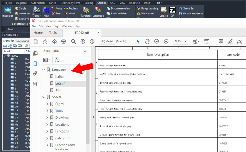
Multilanguage Pdf
The Save multi-sheet to PDF function allows you to obtain the PDF file of the multi-sheet wiring diagram with different customizations given by the many options and preferences available.
With the new version, in particular, it is possible to generate a PDF with texts in multiple languages.
In order to take advantage of this functionality it is necessary to have translated the diagram in Multilayer mode.
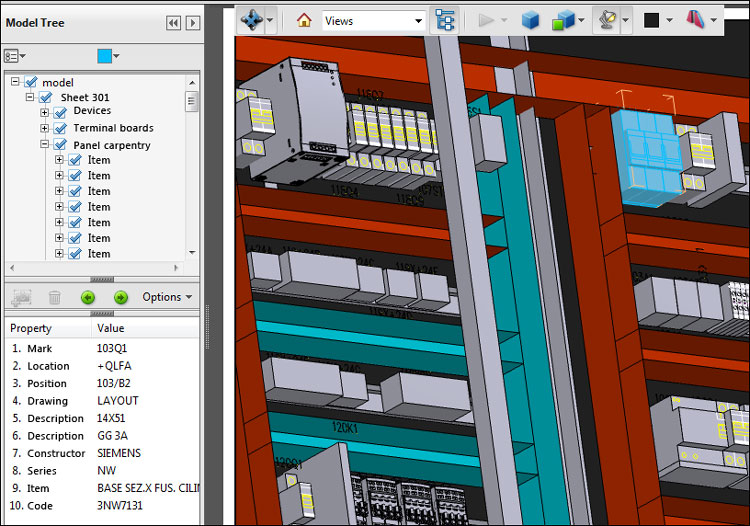
PDF 3D
A 3D PDF is a pdf file that incorporates one or more solid graphics templates that can be viewed with the Adobe PDF Reader © application. The 3D model represents, within the pdf, an active content as it is possible to zoom, pan, rotate, change views and visual styles.
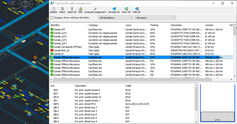
Editing of the sections of the defined ducts, verification of cramping and automatic assignment of typologies
The new management window for cable holder path allows you to obtain an overview of the status of the conduits of a planimetric drawing.
Management of cable holder path is the tool to be used after the drawing of the conduits and the insertion of the units cables processed with the electrical grid calculation tools.
The assignment of automatic sections guides the designer in selecting the appropriate cable holder based on the situation. It is also possible:
• check the filling status of the sections of the conduits;
• modify the information assigned to the conduits on all the straight elements of the selected sections;
• start the 3D development of the conduits and the rendering view.
Improvements in the compositions library and insertion of symbols in boxes
The Align boxes with the same elevation option is now also available; it is useful for compositions of several boxes arranged side by side. If the option is active, when a composition is inserted in the floor plan, the boxes that have the same elevation value are drawn side by side.
Electric grid utilities and conduits management review
Revision of the Electrical grid management functions in order to improve operations on complex systems.
The insertion of the unit cables in the conduits drawn in the plan is done with the electrical grid management tools.
A new option allows to obtain detailed routing, specifying which cable holder sections to consider for the cables of certain units. For this purpose it is necessary to draw the conduits on distinct layers and specify the right layer in the units data.
New symbols legend
The new symbol legend shows the configuration window used for other tables, with the columns that can be sorted, deactivated, size and column settings and profiling.
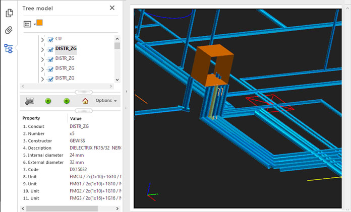
3D PDF of the planimetric drawing
The Save 3D PDF function of the floor plan produces a PDF file with a 3D model of the drawing, with particular attention to the representation of the ducts in three-dimensional format. The published objects are grouped in the model tree, in nodes corresponding to the layer they belong to in the drawing.
Save project WorkSet
For the needs of using PDM software it is now possible to manage the electrical automation project, as a single document file, which can be included in the backup managed by a server and can be opened with the classic double click, monitoring the time of use by an operator.
See all new features 2021:


