New features 2025 Series - Electrical grid calculation
Electro Graphics releases the latest 2025 Series of electrical and photovoltaic design software. Here are the most important features and enhancements introduced about Electrical grid calculation in the software Ampère line and EGlink.
See all new features 2025:
Download brochure Electro Graphics New features 2025
Improved interface and operating speed
The Ampère 2025 line provides enhanced performance for increasingly complex projects.
The continuous evolution of the software, which culminated in Ampère Evolution and the dedicated load flow models, has led to a significant increase in available functionality and verification. At the same time, the size of projects has grown exponentially - think of photovoltaic power plants of tens of megawatts.
To meet these challenges and ensure an increasingly smooth user experience, we have focused our efforts on performance optimisation.
• Optimal utilisation of hardware resources: the 2025 line was designed to maximise the use of multi-core processors, allowing complex calculations to be performed in parallel and drastically reducing processing times.
• State-of-the-art algorithms: we have implemented algorithms with computational complexity O(nlogn), guaranteeing excellent performance even for large grid sizes.
• Targeted optimisation: Ampère internal algorithms have been carefully optimised for different types of networks, with a focus on calculating faults, voltage drops and load flow.
Thanks to these innovations, the fourth option (multi-thread O(nlogn) complexity) offers a significant performance improvement for a wide range of applications.
Definition of supply points with electrical parameters of the cutting section
The new Cutting Section window in the Supply Data is designed to simplify the design of extensions to existing installations. When starting from an already constructed panel, it is essential to consider the specific characteristics of the upstream installation to ensure correct and safe dimensioning.
The following information can therefore be added
• Voltage drop: indicates the maximum permissible voltage drop for the existing installation. This information allows you to further limit the voltage drop of the new section, ensuring that the overall value remains within the permissible limits.
• Overload current: defines the maximum current that can flow in the existing installation without triggering the protections. This information is essential for correctly sizing the power lines of the new section.
• Presence of UPS: if there is a UPS in the installation, you can specify its short-circuit current. This information allows you to coordinate the protections of the existing installation with those of the new section, guaranteeing selectivity in the event of a fault.
• Differential protection: means the presence of differential protection in the existing installation. This information allows you to check the compatibility of the new section with the existing protection and to ensure safety against earth faults.
• Interrupting capacity: defines the maximum fault current that can be interrupted by the protections upstream of the installation. This information allows you to correctly size the protections of the new section, avoiding unnecessary oversizing.
With this additional data you can:
• Increase the accuracy of calculations: dimensioning will be more accurate, avoiding over- or undersizing of power lines and protections.
• Improve plant safety: the new section will be perfectly integrated into the existing plant, guaranteeing maximum protection against faults.
• Save time and resources: simplified calculations will allow you to reduce design time and optimise the use of materials.
Additional information can be found directly in the supply panel data drawn in Knitting and in the printout information.
In conclusion, the new Cutting Section is a useful tool for anyone involved in the design of extensions to existing installations.
Thanks to this functionality, more accurate, safe and efficient dimensioning is guaranteed.
Management of locked and unchangeable panels in the design mesh
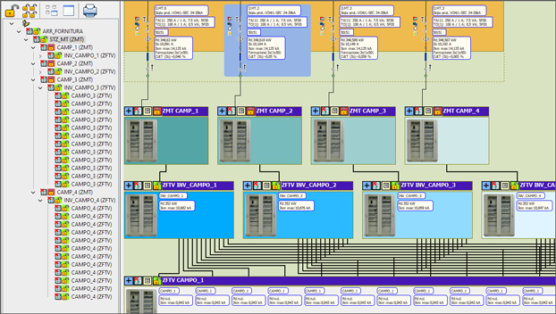
The Panels tab provides a clear and intuitive overview of the entire electrical schematic of your project and acts as a map that allows you to quickly move from one point to another within the plant.
• Schematic at a glance: the Panels tab shows a visual and simplified representation of the entire installation, making it easy to navigate between the different panels.
• Quick selection: with a simple click, you can centre the electrical diagram on the panel you are interested in, automatically updating all the information displayed.
• Detailed information: each panel is represented by an icon providing information on its status, such as the presence of carpentry data or whether it has been locked or unlocked.
To “lock” a panel means to prevent its modification. This functionality is particularly useful when:
• you are working on an extension project: you can lock the panels of the existing installation to avoid accidental changes and concentrate on the new part of the project;
• you want to improve performance: locking panels that do not require modification can speed up calculations.
When a panel is locked, its data cannot be modified: the unit information contained in the panel cannot be changed. The calculation is frozen: the software uses the last available data for the locked panel. In addition, certain functions such as automatic cable assignment or voltage drop optimisation are disabled for the locked panel.
At any time, the general command Calculate all allows you to update calculations even for locked panels. In this way, it is possible to update the information on the cut-off sections, i.e. the parameters defining the connection between active and blocked panels. It is important to remember that even if a panel is blocked, electrical checks are still carried out to ensure that the installation complies with the standards.
View of the grid in compressed mode with closed panels
The compressed view, already present in previous versions, has been significantly improved to provide you with an even more intuitive user experience. You can now enjoy a clearer representation of panels with multiple inputs, making it easier to navigate and have a better understanding of the entire system.
Position yourself comfortably in the Panels tab and, with a simple click, switch between the normal and the compressed view. The second one is optimised for large projects, as it allows you to reduce the size of the mesh and focus on the active panel.
The compressed view provides all the essential information on the main units of each panel, directly on the mesh. you can customise the information displayed via the Labels window and obtain a clear, graphic representation of the project at a glance.
Setting the mechanical opening times of MV protections
The elimination of a medium voltage short circuit takes a certain amount of time, which is influenced by several factors: the response time of the protection, any delays introduced to ensure selectivity, and the time it takes for the circuit breaker to open.
Ampère 2025 Professional or Evolution version takes all these aspects into account.
You can customise the switch opening time in the software settings, or use the default value of 70ms.
This means:
• Accurate calculations: the tripping curve graphs and verifications take the breaker opening time into account, guaranteeing reliable results.
• Flexibility: the software can be adapted to specific needs, changing the breaker opening times according to the project data.
• Regulatory compliance: calculations comply with the relevant technical standards, ensuring plant safety.
In summary, Ampère 2025 Professional or Evolution version offers a complete tool for analysing and designing medium voltage protection systems, taking into account all factors affecting tripping times.
MT cell archive with parametric macroblocks for single-wire diagram
Ampère 2025 Professional or Evolution version offers a new functionality for creating medium and high voltage single-wire diagrams.
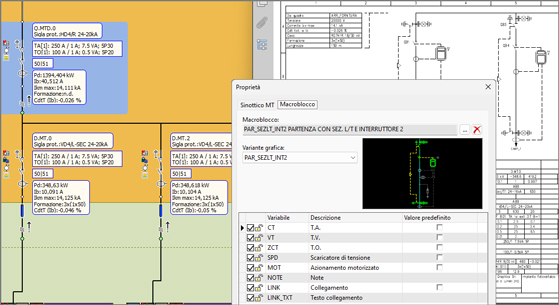
Thanks to the new MT synoptic assignment functionality, it is possible to automatically generate detailed diagrams of MT/AT cells by simply selecting a predefined template from the archive.
For each unit of type MV/HV cell present in the planned power grid, it is possible to select a parametric macroblock representing the synoptic diagram of the cell.
Each macroblock is a pre-configured model in the archive that can be customised according to the specific characteristics of the cell.
After association of the macroblock, the configuration of the model by means of options to be activated or deactivated according to the characteristics of the MT/AT cell in the project, determines the customisation of the single-wire diagram by adding or removing components such as current transformers (CT), voltage transformers (VT), protective relays (ZCT), voltage surge arresters (SPD) and motorised drives (MOT). In just a few clicks, you get a precise and professional single-wire diagram.
Improvements in the visualisation and profiling of selectivity curves
The new version of Ampère offers new features to make the analysis of selectivity curves even more intuitive and customised.
It is now possible to:
• Instantly highlight the curve of your interest by simply hovering the mouse over the corresponding label.
• Create customised labels to associate calibration values directly with the curve, simplifying comparisons.
• Evaluate the curves in relation to the most relevant short-circuit currents for each threshold, thanks to a new analysis tool.
More flexible fault analysis
After performing a network calculation, you can now select the type of fault you wish to analyse:
• All faults: for a complete overview.
• Phase faults only: for a focused analysis.
• Ground faults only: to assess the protection against ground faults.
Definition of the insertion point of indirect TA / TO
Ampere's new functionality represents a significant step forward in the design and management of electrical protection systems, offering greater flexibility, ease of use and reliability.
Ampère introduces a new feature that greatly simplifies the process of coordinating protection in complex installations with non-standard measuring points.
When transducers are not positioned directly at the point to be protected, this is known as an 'indirect insertion point'. While this configuration offers flexibility, it requires careful consideration to ensure that the protection functions correctly.
Ampère's new functionality allows the coordination between protectors and transducers to be defined easily and intuitively, even in complex configurations. Thanks to this tool, it is possible to guarantee maximum selectivity and reliability of the protection system, reducing power loss times to a minimum in the event of a fault.
To create a coordination, simply assign a protection to the unit, assign a transducer to the unit without protection and create the protection-TA/TO coordination. Ampère checks the compatibility of the data and automatically generates the necessary configuration.
For example: in an industrial installation with an MV/LV transformer, this function can be used to coordinate the differential protection of the transformer with the maximum current protection of the low-voltage line, even if the homopolar current transformer is downstream of the transformer.
Assignment of CT / TO to LV units and protections
Ampère now makes it easy to define current and voltage transformers (CTs/VVs) for low-voltage units as well.
The procedure is identical to that used for medium voltage: simply go to the Protection section in the unit data and enter the TA/TV data.
Low-voltage transformers can be coordinated with medium-voltage protections, ensuring complete protection of your installation.
Ampère will automatically adjust the values according to the transformation ratio between the two voltage levels.
To simplify the process, CT/TV saturation checks, typical for medium voltage, are not required for low voltage units.
Adaptations to the forthcoming new CEI 64-8 Ed.9
Ampère has incorporated the latest changes in CEI 64-8, the standard regulating electrical installations. In particular, new verifications have been introduced to ensure the safety of people in the event of an earth fault.
Verification of indirect contacts: new rules
The new standard has changed the maximum time allowed for the interruption of an earth fault, especially to protect wall sockets and portable equipment. Ampère allows you to automatically check whether your installation complies with these new limits.
Conversion devices: a key role
If there are power electronic converters in your installation, such as photovoltaic inverters, the new standard imposes specific requirements to limit the voltage in the event of a fault. Ampère recognises these devices and verifies whether they are able to guarantee safety.
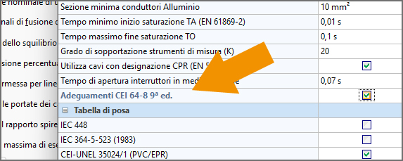
To activate the new checks, simply select the option Adaptations CEI 64-8 9th ed. in the project properties. Ampère will automatically perform all the necessary checks and report any non-conformities.
Extending and updating the device archive
New series have been integrated for all types of devices that can be used in a photovoltaic system.
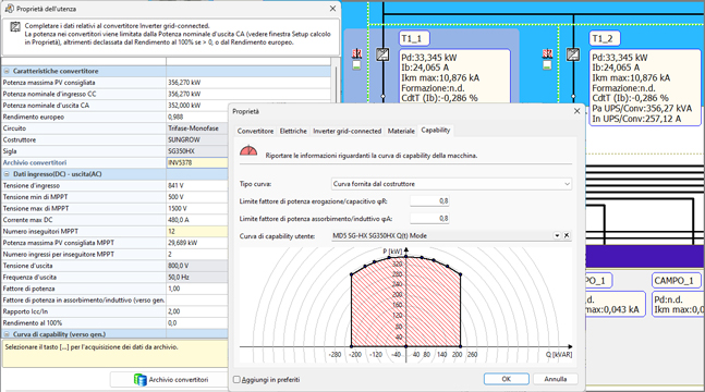
Archive P/Q capability curves according to manufacturer's model, with points curves
Ampère 2025 introduces a new feature that enables the accurate definition of P/Q curves of electrical devices such as generators, inverters and storage systems. This feature allows the dynamic behaviour of electrical systems to be accurately simulated, taking into account the operating limitations of the components.
Thanks to the possibility of defining customised curves for each device, accurate analysis is possible:
- The optimal dimensioning of installations
- The interaction between generators, loads and storage systems
- The impact of grid variations on system performance
P/Q curves, which describe the relationship between active and reactive power, can be imported directly from manufacturers' catalogues or created manually by the user. The application supports the import of data in different formats and allows parametric curves to be defined as a function of physical quantities such as voltage and temperature.
Ampère Evolution: assignment of P/Q curves for points to elements in the grid
Ampère Evolution 2025 offers unprecedented flexibility in defining the behaviour of electrical equipment. By directly assigning P/Q curves to individual components (generators, inverters, storage systems), it is possible to accurately simulate system performance under different operating conditions.
P/Q curves, which describe the relationship between active power and reactive power, can vary according to parameters such as mains voltage and ambient temperature. Ampère Evolution makes it possible to manage families of curves so that the most appropriate curve is automatically selected according to the operating conditions.
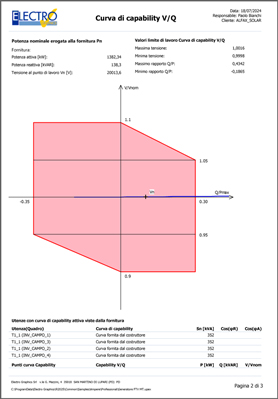
Ampère Evolution: generation of the plant's V/Q capability curve
Ampère Evolution 2025 Ampère Evolution 2025 automatically calculates the V/Q capability curve, an essential tool for assessing the impact of generation plants on the power supply.
This curve indicates how the grid voltage varies with the reactive power produced by the plant, helping to prevent overvoltage problems.
The V/Q curve allows you to identify operating conditions that could cause an excessive increase in mains voltage, potentially harmful to electrical equipment and the grid itself.
Thanks to the V/Q curve, you can correctly size the reactive compensation systems required to keep the voltage within permissible limits.
Ampère Evolution guarantees compliance with current regulations ( attachment A.17 and A.68), simplifying the authorisation process for installations.
EGlink: BIM integration between Revit© MEP and - Ampère Professional/Evolution
EGlink is an interchange plug-in between Autodesk Revit and Ampére Professional/Evolution and represents the Electro Graphics's response to BIM (Building Information Modeling) process mode. Here are the most important features and enhancements introduced in EGlink 2025.
Extension of functions and adaptation to Revit 2025
EGlink 2025 is compatible with Autodesk Revit version 2018 to version 2025.
See all new features 2025:
Download brochure Electro Graphics New features 2025


