
New features 2024 Series - Electrical CAD
Electro Graphics releases the latest 2024 Series of electrical and photovoltaic design software. Here are the most important features and enhancements introduced in the electric CAD CADelet, iDEA, Eplus.


See all new features 2024:
Download brochure Electro Graphics New features 2024
Eplus and iDEA are based on the new AutoCAD OEM 2024 engine
One of the main novelties of the 2024 version of iDEA and Eplus is the update from version 2023 to version 2024 of the Autodesk AutoCAD® OEM engine on which the two electrical CADs are based.
Below we focus only on the most significantly useful features for use in iDEA and Eplus , introduced.
PDF Generation with Searchable Non-TrueType Fonts
This feature is useful for designers who use AutoCAD SHX fonts in their drawings. Previously, text using these fonts was not searchable or selectable in PDF files.
With this new feature, you can store text objects that use SHX fonts as hidden text when the drawing is exported to a PDF. This makes the text searchable and selectable in the PDF.
To use this feature, you need to set the system variable PDFSHX to 2. You can do this by typing the command "PDFSHX" at the command prompt and typing "2".
Once the PDFSHX variable is set to 2, you can export the drawing to a PDF file with the CREAPDF command and select the "Save text as hidden text" option.
The text in the PDF will now be searchable and selectable.
Smart and Automated Insertion of Generic Blocks, with Interpretation of Previous Usage Situations
This feature is useful for designers who need to insert generic blocks repeatedly. The block placement system learns how existing block instances are placed in the drawing to deduce the next placement of the same block.
For example, if you have already placed a chair block near the corner of a wall, when you insert another instance of the same chair block, the CAD automatically positions the chair as you move it near a similar corner.
You can click to accept the suggestion, press CTRL to move to other suggestions, or move the cursor away to ignore the current suggestion. To temporarily disable suggestions during block placement, hold down SHIFT+W or SHIFT+[ while inserting or moving the block.
CADelet supports AutoCAD 2024
• CADelet line software is now compatible with AutoCAD version 2018 to 2024 64 bit.
• Smart line software is now compatible with AutoCAD LT version 2018 to 2019 64 bit.
Saving and downloading project data in EG Cloud, with the possibility of sharing with other operators
EG Cloud is a cloud storage and sharing service, managed through the software infrastructure and data center of Acronis®, that Electro Graphics makes available to users of its software that are under warranty and/or maintenance contract.
EG Cloud offers a range of features that allow users to save, share, and access their data securely and easily. These features include:
• Uploading projects to your cloud space, which can be organized into folders and subfolders.
• Downloading and opening projects that have previously been uploaded to EG Cloud.
• Navigating your cloud space through the EG Cloud browser.
• Creating sharing links for projects.
• Accessing your cloud space through the Acronis web portal.
• Accessing your cloud space from mobile devices through the Acronis Cyber Files app.
EG Cloud is a valuable tool for users who want to have secure and easy access to their data. Its features make it simple and quick to save, share, and access projects, even remotely.

Here are some of the benefits of using EG Cloud:
• Security: Data is stored in a secure cloud that is protected by Acronis®.
• Accessibility: Data can be easily accessed from any device connected to the Internet.
• Flexibility: Data can be easily shared with other users.
• Organization: Data can be easily organized into folders and subfolders.
• Efficiency: EG Cloud saves time and money by eliminating the need to purchase and manage your own server.
If you are looking for a secure, easy, and flexible way to store and share your data, EG Cloud is the ideal solution.
EG Cloud cloud saving and sharing service New feature 2024
Recovery in CAD of annotations made with the Acronis mobile app, on PDF in the cloud, for collaborative editing
EG Cloud is a tool that facilitates the sharing of PDF files generated by Electro Graphics CAD software (CADelet, iDEA, Eplus, Smart) in order to exchange information about the electrical diagram through annotations that can be added to the drawing published in the PDF itself.
It is possible to publish a PDF file from CADelet, iDEA, Eplus, Smart in EG Cloud using the Save to PDF function (SALVAPDF command) and selecting the "Publish PDF file in EG Cloud" option in the dialog box. Once the file is published in EG Cloud, it can be accessed via the Acronis Cyber Files app and annotations can be added.
Acronis Cyber Files is a mobile app provided by Acronis, available for Android and iOS, that gives access to the EG Cloud storage space and the content it contains. Through it, it is possible to open the projects published in PDF format from the CAD environment in EG Cloud and add comment notes and other graphical elements useful for sharing information between those who consult the document. The changes can then be updated in the CAD drawing using the Import annotations from PDF function, available in CADelet, iDEA, Eplus, Smart.
This feature allows users to collaborate more efficiently and productively in the development of electrical diagrams, exchanging information quickly and easily.
Management of workset files, as complete containers of project files (dwg + schema data), for optimal data passage to PDM systems or the cloud
Workset files are a way to organize project files in AutoCAD. They can be used to store all the files needed for a project, including DWG files, schematic data files, and other related files. Workset files can be used to improve collaboration, data management, and version control.
Electro Graphics CAD software (CADelet, iDEA, Eplus, Smart) supports this working method. These software allow you to create workset files and share them with other users, giving them access to all the files needed for the project. Workset files can also be used to improve version control, allowing users to track changes made to project files.
Workset files are a powerful tool that can be used to improve collaboration, data management, and version control. They can be used to move data to PDM systems or the cloud, simplifying the storage and management of project data.
Possibility of interfacing with Autodesk Vault PDM through a direct connector (optional), with saving and downloading of schematic files and associated PDF
Electro Graphics CAD software (CADelet, iDEA, Eplus, Smart) allows for integration with Autodesk Vault project files. To do this, it is necessary to activate an interface module and some commands that facilitate the archiving of files in Autodesk Vault.
 Autodesk Vault is a document management software that allows companies to organize project data, manage documentation, and track revisions and other development processes. Autodesk Vault is a data management tool integrated with the major Autodesk products.
Note. The Autodesk Vault interface service is optional. You must contact Electro Graphics for further commercial information.
The following functions are available in CADelet, iDEA, Eplus, Smart ; they can be started by typing the commands at the command line.
Save schema to PDM
Run this function (command PDMSAVE) to first archive a project in Autodesk Vault. After the login dialog box, the Vault folder navigation window will appear. Select the desired folder and confirm.
The schema file (.schx) and all drawing files (.dwg) will be saved in the Vault as associated files.
Extraction (checkout) of a schema
This function allows you to extract the schema to access the project modification. At the command line, type PDMCHECKOUT. The extraction of the schema file and all related drawings takes place in the Vault working folder.
Archiving (checkin) of a schema
At the end of the design, to archive the project, run the command PDMCHECKIN. A dialog box allows you to attach a comment to the new file revision. A checkbox allows you to keep the extracted file to make further changes. Otherwise, the project files are released and can be extracted again by a new operator.
Management of global system parameters and specific schema parameters with definition of any variables derived from them
The use of Schema Parameters introduced in the CAD electrical CADelet, iDEA, Eplus, Smart offers the designer advanced control over the customization and automation of labels associated with the attributes of graphic blocks.
This innovative feature allows you to create intelligent labels that can be simple variables, complex formulas or conditional values, offering high flexibility in the creation of customized electrical diagrams.
Schema Parameters are intelligent labels that can be assigned to the attributes of graphic blocks in the electrical diagram. They can condition the appearance and behavior of the elements of the diagram.
Schema Parameters represent a powerful tool for the customization and automation of electrical diagrams. Just experiment with the various options available to discover how this feature can simplify the job and offer greater flexibility in the creation of customized electrical diagrams.
The introduction of Schema Parameters in electrical schematic CAD offers several significant advantages for the centralization and conditioning of labels. Here are some of the main advantages.
Flexible customization
Schema Parameters allow the designer to customize labels flexibly according to their needs. They can insert variables, complex formulas or conditional values, allowing labels to be adapted dynamically to the specifications of the project.
Automation of calculations
The ability to use complex formulas within Schema Parameters allows for the automation of calculations associated with labels. For example, you can create a formula that automatically calculates an output voltage based on the input voltage and the characteristics of the circuit components. This significantly reduces the risk of manual errors and accelerates the design process.
Consistency and cohesion
With Schema Parameters, it is possible to ensure uniform consistency and cohesion within an electrical diagram. By using common parameters for similar or related labels, you can maintain a consistent style and reduce the possibility of data entry errors.
Simplified updates
If you need to make changes to a label or formula within a diagram, the centralization of Schema Parameters simplifies the update. By changing the value of a parameter, all labels connected to it will be automatically updated, avoiding the need to manually modify each individual label.
Adaptability to project changes
During the development of an electrical diagram, changes or updates to the project specifications may occur. By using Schema Parameters, you can manage these changes in a centralized, efficient and fast way. Simply modify the values of the parameters or the formulas, and all connected labels will automatically adapt to the new conditions.
If you want to use a Schema Parameter as a variable, simply assign a specific value to the parameter. For example, you could create a parameter called "Input Voltage" and assign it the value "230V". This value can then be retrieved and used in other labels or formulas within your diagram.
A parameter can also be assigned to a variable in a parametric macroblock: the assignment rules of such variable to the attributes then transfer the information to the affected attributes.
In summary, the centralization and conditioning of labels through Schema Parameters allow for greater flexibility, automation and consistency in the development of electrical diagrams. This function improves work efficiency, reduces errors and simplifies change management, contributing to a faster and more accurate design process.
Global parameters
Schema parts saved in the Sheet Library and parametric macroblocks can include predefined parameters.
This allows designers to find the parameters associated with the element already listed when they select it from the library and insert it into the schematic.
These parameters, not related to a specific schema, are defined as Global parameters. They are automatically called when you want to assign a parameter in the editing phase of a macroblock or a sheet in the library.
Once a schematic part has been inserted into the drawing, you can modify the parameter values to adapt them to the project specifications. You can assign custom values to variables, modify formulas, or select the correct options for conditional parameters.
The integration of Schema Parameters in schematic parts saved in the library offers several advantages.
• Time saving: Designers do not have to manually create parameters for each element inserted into the schematic. They already find the related parameters listed when selecting a schematic part from the library.
• Consistency: Using predefined parameters in schematic parts promotes consistency in the use of parameters within an electrical schematic.
• Customization: Operators can modify the parameter values according to the needs of their project, ensuring greater customization of the labels associated with the attributes of graphic blocks.
When you start a new schematic, all global parameters are automatically imported into the new project. If the global parameters have been updated, use the Import Global Parameters command to update the current project.
Generation of relationships and formulas between parameters with use of the result in variables
There are three types of parameters: input, formula, and conditional list.
Input parameters
Input parameters are the most common type of parameters. They can be modified directly by the user and can contain text, numbers, or Yes/No values. If the type is text or number, it is possible to define a list of predefined values to draw from.
Formula parameters
Formula parameters are expressions that can be a combination of parameters, constants, and functions. For example, you can create a parameter called TotalCurrent and define a formula that sums the currents of other components in the schematic. This formula will be calculated automatically whenever the value of one of the reference components changes.
Conditional list parameters
Conditional list parameters allow you to define conditional values based on other parameters and conditions. For example, you can create a parameter called TerminalCode with different options linked to the target market of the schematic (European, Asian, American). Based on the selection of this parameter, it is then possible to automatically set other parameters or modify the formulas to adapt to the type of value used.
Formulas and conditions between parameters with use of the result in variable management
In the Formula and Condition fields, parameters and constants can be combined to form complex expressions that can be adapted to respond to widely customizable logic.
It is important to note that parameters are processed in the exact order dictated by the index: you cannot use a parameter on a formula or expression before its definition or at an index lower than the one in which it is defined.
Using parameters or calculated variables in parametric macroblocks and attributes
Using parameters in symbol attributes
The quickest way to use a parameter in the scheme is to drag and drop the desired parameter directly onto the attribute editing mask.
The related attribute editing window box becomes read-only and changes color to indicate that the value is related to a parameter.
From the context menu it is possible to remove the parameter from an attribute, or call up the parameter list window and assign or modify it.
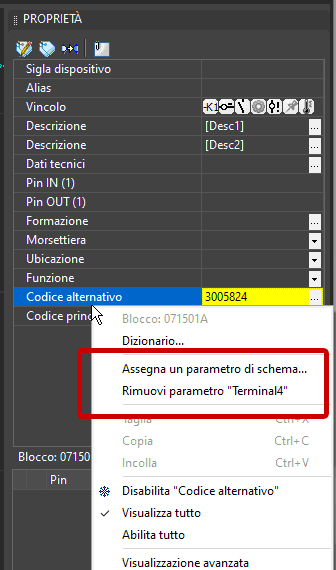
Similar interface for assigning and removing a parameter can be found in the table attributes editing (DDT command) and the macroblock variables editing window (DDAMACRO command).
The translation is literal and accurate. The only change I made was to replace the Italian command names with their English equivalents.
Using parameters in parametric macroblock management
Similarly to what is reported for symbol attributes, it is possible to assign the value of schema parameters to the variables of parametric macroblocks. It is possible to assign a parameter to a macroblock variable:
• in the electrical schematic drawing;
• in the macroblock drawing saved in the Macroblock Library;
• in the Fast Builder project xls spreadsheet.
Ability to use parameters and variables in the management of sections and wire data
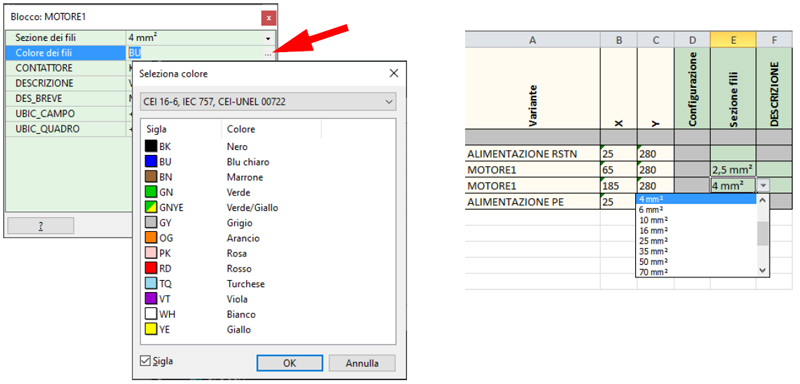
The special variables #SECTION and #WCOLOR are used to manage the wire section and conductor color, respectively.
The value of these variables can be modified in the graphical environment using the macroblock variables editing command (DDAMACRO command) or the Fast Builder project spreadsheet.
In the drawing of electrical schematics, the value of the wire section is conveyed through the color of the lines that make up the wires themselves. The conductor color assigned to the wire is instead an internal data that can be viewed and edited using the SEZ command or the Properties palette.
Vario: integration and use of defined parameters to condition options and obtainable profiles
 If the license in use includes the full version of Vario (the limited version is always available in CADelet, iDEA, Eplus, Smart), you can access the Options tab.
With the introduction of Schema Parameters, an Option can also be activated based on a condition based on an expression composed of parameters. The Conditional Option checkbox enables the text box where the operator can enter the condition that will be evaluated every time an input parameter is changed.
Conditional options are not explicitly mentioned in machine profiles because their presence is delegated to the evaluation of the condition.
Use of schema parameters in Vario options
Schema Parameters are integrated with the Vario application through Conditional Options and saving them in Profiles. In fact, it is possible to save the value of all the values of the input parameters for each Profile. Applying a Profile to the schema is equivalent to resetting the parameters with all the values saved for that Profile.
Export to spreadsheet and Import
It is possible to export and import the parameter list using the Export to xls and Import from xls functions, found in the Utilities menu of the Vario Parameters page.
The export function, to xls file or directly in Excel, reproduces the list of only parameters of type Input Parameter on a spreadsheet. The columns of the list correspond to the parameter data (Name, Description, Group, Value).
The import function allows you to import the parameter list present in the spreadsheet. The changes to the Description, Group, Value data will be imported into the Vario project variables. For each row in the spreadsheet for which the Name data is not found in the Vario parameter list, a new corresponding parameter is created.
Fast builder: managing the color of wires defined within parametric macroblocks
Parametric macroblocks are a powerful tool that allows you to create drawing blocks that can be customized to meet the needs of the project. One of the most useful features of parametric macroblocks is the ability to manage the wire section and conductor color.
The special variables #SECTION and #WCOLOR are used to manage, respectively, the wire section and conductor color.
The value of these variables can be modified in graphical mode using the macroblock variables editing command (DDAMACRO command) or through the spreadsheet of a Fast Builder project.
In the drawing of electrical schematics, the value of the wire section is conveyed through the color of the lines that make up the wires themselves. The conductor color assigned to the wire is instead an internal data that can be viewed and edited using the SEZ command or the Properties in-line palette.
In order to allow the section to be modified by the special variable #SECTION, the wires within the macroblock stored in the Parametric Macroblock Library must assume Wire Section "[UNDEFINED]".
It is important that the color dedicated to the undefined section corresponds to the one used in the work project settings.
The value assigned to the special variable #WCOLOR will also be assigned to all wires in the macroblock stored in the Parametric Macroblock Library that do not have the given color assigned.
The variables #SECTION and #WCOLOR are a powerful tool that can be used to customize parametric macroblocks to meet the needs of the project.
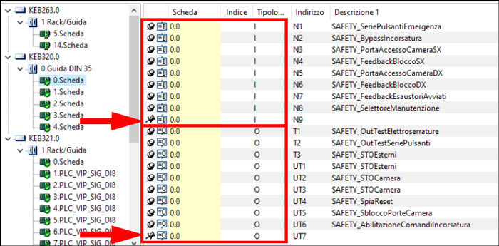
PLC: functionality for re-aggregating operands in order to optimize the use of the used boards
In the sequence of operands of a rack or board ordered by address, there may be unassigned operands. It is useful to be able to move the addresses of these operands to optimize the use of the boards and to operate an operand aggregation based on the elements inserted in the drawing.
The Compact operands utility, which is started from the Tools menu, compacts all operands assigned to a symbol in the drawing by address, moving the unassigned operands to subsequent addresses.
The assigned operands, grouped by type, occupy the selected boards of the same rack based on the group sorting.
Auxiliary operands are excluded.
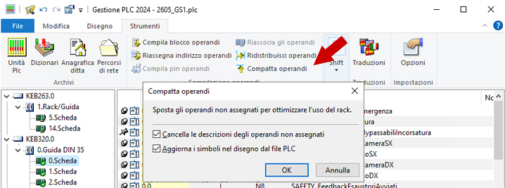
When starting the function, you can select the following options to update the open drawing:
• Delete descriptions of unassigned operands: the descriptions of unassigned operands are deleted.
• Update symbols in the drawing: all data modified in PLC Management is updated in the symbols present in the open drawing.
As an example, in the following figure you can see the list of operands PLC with two unassigned operands highlighted:
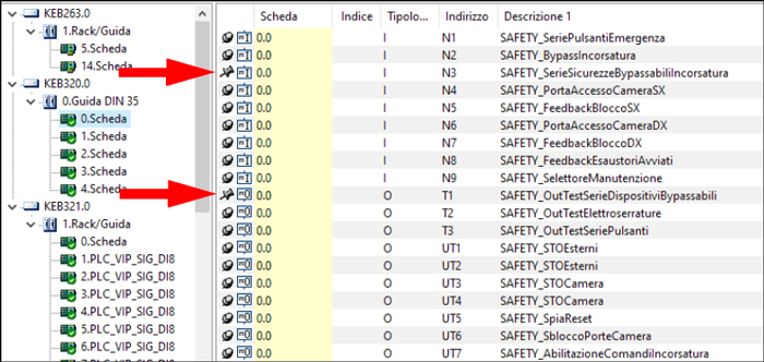
Executing the Compact Operands command moves the two operands to the last available address within the same Board-Type group and deletes their descriptions because the appropriate preference was selected. The assigned operands are compacted.
Retrieval and use of cables already defined on the planimetric on functional diagrams, with import of physical and commercial properties
A new function allows the selective import of cables coded in Network Management into the diagram
During the design of an installation, cables that have already been defined, possibly also sized and coded during the composition and sizing of the electrical network (in the Ampère calculation software or in the planimetric diagram in CAD), can be recalled and used for the functional representation in a multi-sheet diagram linked to the same project.
To import the cables already defined in Network Management, you can use the new Import cables from Networks function in the Cable List dialog box (LCAVI command).
In the Select cables defined in Networks dialog box, select the type of network from which you want to import the cables from the drop-down list.
You can search for the cable by Symbol or Description using the search text box and you will need to place a check mark next to the rows in the list corresponding to the cables you want to import.
Please note that imported cables will be marked with a red box.
Once the cables have been imported, you can assign the imported cables to the connections of the electrical diagram, in the drawing using the Cable Assignment command (SETCAVO command) or through the software Cablo.
Possibility of managing variants on shared auxiliary macroblocks, useful for optimal management of similar circuits
In the design of an electrical distribution board, the drafting of the functional diagrams of the auxiliary elements of the board requires a significant time expenditure, especially for the drawing of details, component labeling, cross-references, and other activities that sometimes bore the electrical designer; such activities do not require high levels of competence, but they require attention to detail and meticulous patience in checking symbols and references in order to allow the builder of the panel to correctly interpret the diagrams with a consequent correct installation of the devices involved.
The electrical calculation software of the XAmpère line allows you to assign a series of auxiliary elements to each power device, equipped with the related functional diagrams, and to obtain the complete development of both the single-line diagram for the power part and the related auxiliary diagrams, such as for example the management of signaling and alarm lights, the state of the devices, the opening and closing timers, auxiliary relays for crepuscular lights and more.
Improvements to the automatic generation of single-line diagrams
Choice of graphical variant of auxiliary functional diagram macroblock
For the automatic drawing of the auxiliary functional diagram, it is now possible to choose the graphical variant of the macroblock that implements the auxiliary functional diagram associated with the consumer.
The choice of the graphical variant can be made for macroblocks with the "Auxiliary functional diagrams" type of use and compatible with the consumer's protection/cutting device that have two or more associated graphical variants.
To choose the graphical variant, you must open the "Macroblocks" dialog box and select the desired macroblock. On the "Properties" tab, in the "Graphical variant" section, you can select the desired graphical variant from the drop-down menu.
Once the graphical variant has been selected, you can insert the macroblock into the auxiliary functional diagram. The macroblock will be inserted into the diagram using the selected graphical variant.
For the automatic drawing of the single-line diagram for consumers for cabinets, which is started from Units diagram management, a new option is available that concerns the insertion of terminals on the departures for other cabinets. The new option Do not trace equipotentiality in the departures avoids the insertion of the equipotentiality symbol on the consumers exiting the electrical panel.

Vincolo per l’esclusione dal calcolo di sovratemperatura
Nei simboli di CADelet, iDEA, Eplus, Smart l’attributo Vincolo (etichetta VINCOLO) viene utilizzato per vincolare o imporre certe condizioni. Un nuovo vincolo permette di ignorare la potenza dissipata del componente nel calcolo della sovratemperatura quadro. Il caso tipico per cui è utile questo vincolo è quello dei dispositivi di protezione associati alle utenze di tipo SPD: in tal caso l’utenza è passiva e non concorre ad alcuna dissipazione.
Constraint for exclusion from overheating calculation
In the symbols of CADelet, iDEA, Eplus, Smart the attribute Constraint (label VINCOLO) is used to constrain or impose certain conditions. A new constraint allows you to ignore the dissipated power of the component in the calculation of the overheating of the cabinet. The typical case for which this constraint is useful is that of the protection devices associated with SPD type units: in this case the unit is passive and does not contribute to any dissipation.

For SPD units traced automatically in the single-line diagram automatically this constraint is activate.
Improvements in PDF files generated by diagrams and bookmarks included
The Multi-Sheet Save to PDF function simplifies and speeds up the export of a multi-sheet electrical diagram in PDF format. The following are the new features introduced with the 2024 version.
Publish the PDF file to EG Cloud
EG Cloud is also a tool that facilitates the sharing of PDF files generated in CADelet, iDEA, Eplus, Smart to exchange information related to the electrical diagram by means of annotations that can be added to the drawing published in the PDF itself.
With the Save to PDF function, you can publish a PDF file from CADelet, iDEA, Eplus, Smart to EG Cloud and retrieve the annotations added through the Acronis® Cyber Files app.
In the Save PDF window, select the Publish PDF file to EG Cloud option before confirming the save.
Save a group of sheets to PDF
The Save to PDF function now allows you to select a group of sheets on which the multi-sheet diagram is organized and then print only the sheets in the selected group. Similar options allow you to choose one of the locations or functions of the electrical diagram.
The filter options are in the upper left pane. The Filter button opens the selection window. The new group filter lists the groups detected according to the group attribute set in the current title block.
Group attribute. To define a group, it is necessary that one of the attributes of the current title block is set as a Group attribute. For example, if TITOLO is set as the group attribute, the sheets with the same title can be filtered; you can also add an attribute to the title block, called for example GROUP, and use it for custom groupings.
For more information on the group attribute, see "Modifying the title block" in the CADelet/Smart/iDEA reference guide.
In the Select elements to print window, there is the option Save a pdf file for each location/function/group: the selection produces a pdf file for each location, function or group selected. The Separation characters are inserted as separators for the composition of the pdf file name; therefore, the name of the pdf file is composed of the name indicated by the user + separation characters + code of the location/function/group.
Use of bookmarks in diagram files generated in PDF
The Save PDF function now creates a bookmark in the PDF file for each sheet of the open multi-sheet drawing.
See all new features 2024:
Download brochure Electro Graphics New features 2024